Nominal Voltage Architecture (V): 12
Connector & Housing Type : Housing for Female Terminals
Number of Positions : 10
Sealable : No
Operating Temperature Range : -40 – 85 °C [ -40 – 185 °F ]
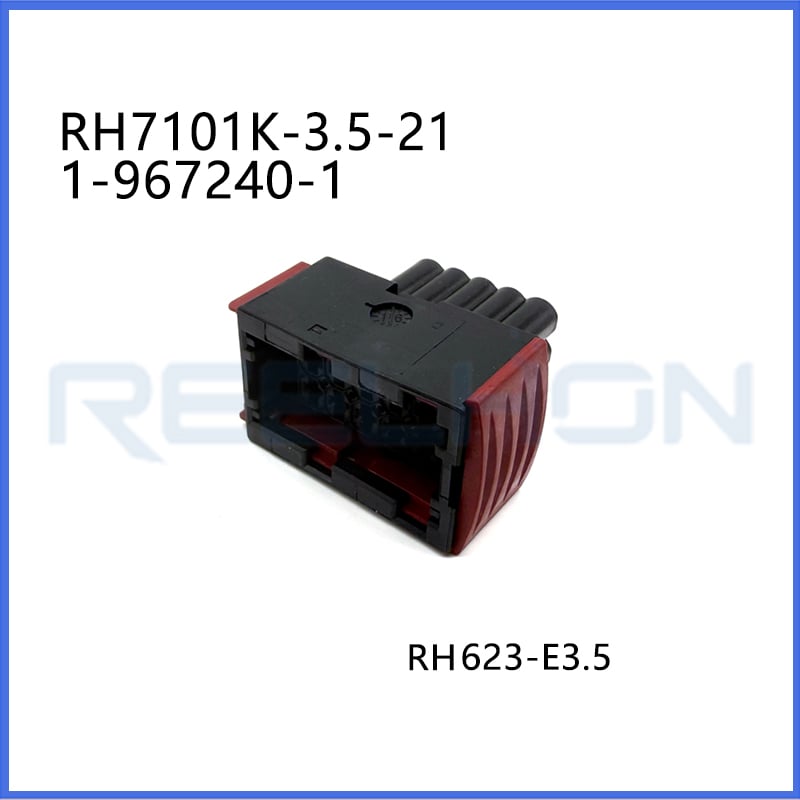
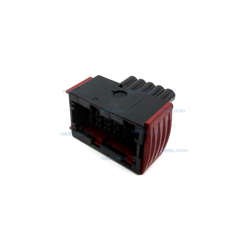
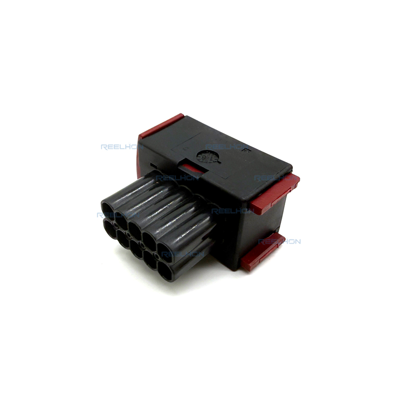
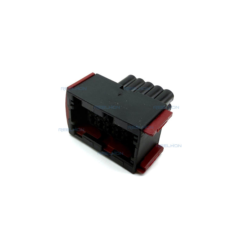
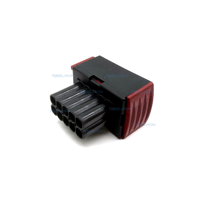
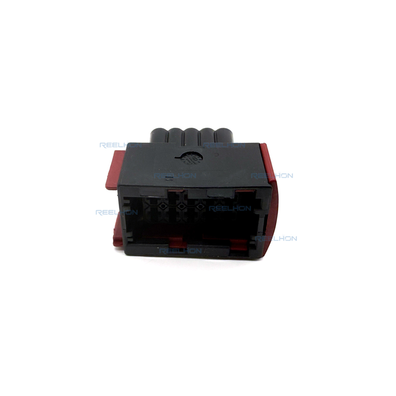
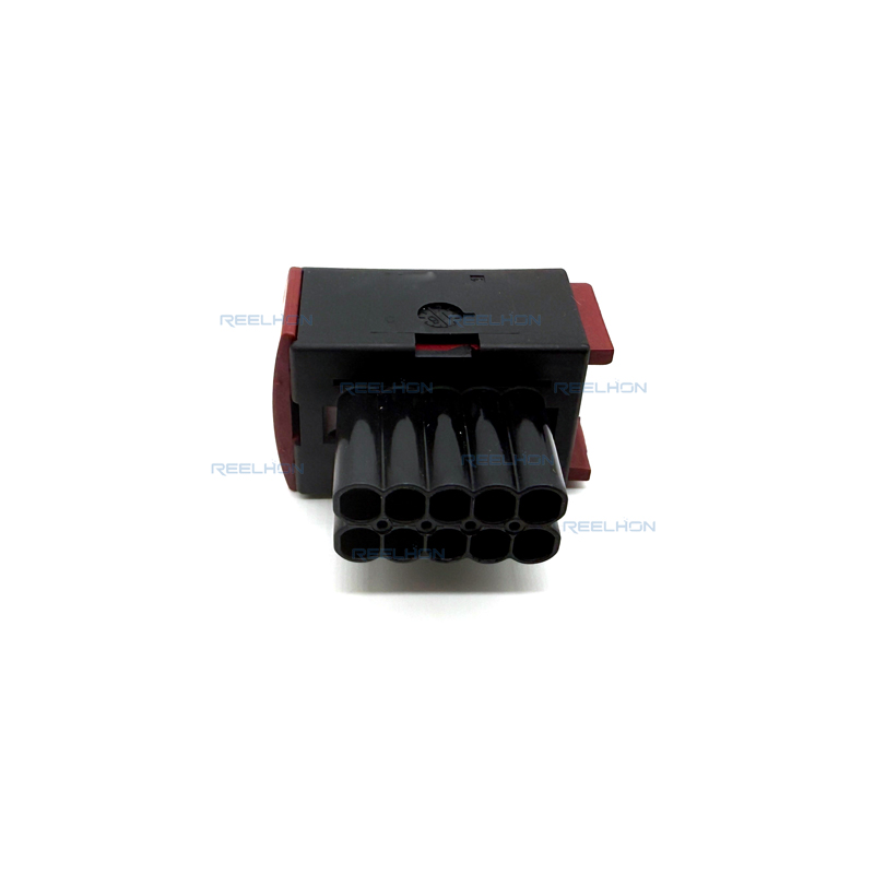
The RH7101K-3.5-21 is a 10-position, 2-row automotive-grade connector housing designed for female terminals. This housing is rated for a nominal voltage architecture of 12 V and is specifically intended for wire-to-board applications. Each contact supports a maximum current rating of 30 A, and the circuit application is explicitly defined as Power (not signal). This makes the housing suitable for power distribution circuits in standard 12V passenger cars, light trucks, and other 12V-based vehicles. The housing is non-sealable (Sealable: No), so it is intended for dry or protected environments where direct water spray, high-pressure washing, or immersion is not expected. The operating temperature range is -40 to 85 °C, which covers typical interior and some underhood applications while being less extreme than 105°C or 130°C rated connectors.
The housing has a rectangular shape and is molded in black primary product color. The housing material is PBT GF30, which is Polybutylene Terephthalate reinforced with 30% glass fiber. This glass-fiber reinforcement significantly increases mechanical strength, dimensional stability, creep resistance, and heat deflection temperature compared to unfilled PBT. The black color is typical for automotive power connectors.
Key mechanical attributes include:
Connector & Keying Code: A1 – this indicates a specific keying or polarization code. Multiple keying codes (e.g., A1, A2, B1, etc.) are often available for the same housing family to prevent mismating between different circuits in the same assembly. This housing uses code A1.
Primary locking feature: Locking Lance – molded into each cavity, this feature deflects during terminal insertion and snaps behind the terminal's shoulder to provide retention.
Mixed & Hybrid Connector: No – all 10 positions accept the same contact size (2.8mm receptacle).
Mating alignment: With – alignment features are included.
Mating alignment type: Keyed – this refers to the keying code system (A1) that ensures the mating header or male housing has a matching keying feature. Only housings with the same keying code can correctly mate.
Terminal Position Assurance (TPA): No – the locking lance is the sole means of terminal retention.
Strain relief: Without – no integrated strain relief; external cable management may be required.
Connector mounting type: Cable Mount (Free-Hanging) – designed for attachment to wires and cables, not for panel or PCB mounting.
The housing accommodates receptacle-type contacts (female terminals) with a contact size of 2.8 mm and a mating tab width of 2.8 mm (0.11 in). The 2.8mm terminal system is a widely used industry standard for medium-to-high current automotive power and ground circuits.
Key electrical parameters:
Nominal Voltage Architecture: 12 V
Contact current rating (max): 30 A per contact
Circuit Application: Power – this confirms the connector is designed and validated for power distribution, not low-current signal circuits.
The 30 A current rating means this housing is intended for circuits such as:
Battery power feeds
Alternator connections
Electric motor supplies (e.g., window motors, blower motors)
Main ground distribution points
High-current accessory circuits
The contact type is Receptacle (female terminal), which receives the mating tab from the corresponding male header. The connector system is specifically Wire-to-Board, meaning it is designed to mate with a PCB-mounted header (not for wire-to-wire applications).
The housing provides 10 positions arranged in 2 rows. Key dimensional specifications are:
Centerline (pitch): 5 mm (0.197 in). This relatively large pitch provides increased creepage and clearance distances, which is essential for 30A power applications to prevent arcing or tracking.
Row-to-row spacing: 6 mm (0.236 in)
Product length: 42.2 mm (1.66 in)
Product width: 37.75 mm (1.49 in)
Connector height: 26.3 mm (1.03 in)
The 2-row configuration with 5 mm pitch and 6 mm row spacing results in a robust, rectangular housing. The length (42.2 mm) is significantly larger than the width (37.75 mm) and height (26.3 mm), giving the housing an elongated rectangular profile. This shape may be designed to fit specific PCB header footprints or harness routing requirements.
The operating temperature range is -40 to 85 °C (-40 to 185 °F), with a maximum rated temperature of 85 °C. Compared to other automotive connectors that may be rated to 105°C, 125°C, or 130°C, this 85°C maximum is more moderate. Key implications:
Lower limit: -40 °C – suitable for cold climates and winter conditions.
Upper limit: 85 °C – appropriate for interior cabin applications (dashboard, door modules, seats), trunk areas, and some mild underhood locations that are not near hot engine surfaces. It is not recommended for engine-mounted or exhaust-adjacent applications where temperatures exceed 85°C.
The housing is explicitly non-sealable (Sealable: No). It does not include provisions for silicone seals, gaskets, or mat seals. Therefore, it must not be used in locations exposed to direct water spray, high-pressure washing, condensation pools, or submersion.
The PBT GF30 (30% glass-filled PBT) material provides excellent mechanical strength at elevated temperatures and good resistance to common automotive fluids such as motor oil, gasoline, diesel, coolant, and salt spray at moderate exposure levels. However, the lack of sealing means fluid ingress into contact cavities is possible if the connector is directly wetted. For dry, protected environments (e.g., inside the passenger cabin, behind interior trim panels, in sealed electrical boxes), this housing delivers reliable performance.
The connector system supports only one mating configuration according to the parameter table:
Wire-to-Board (with a compatible PCB-mounted header that has 2.8mm tabs). Unlike some other housings that also support wire-to-wire, this model is specifically designated for wire-to-board applications.
The primary locking feature is the Locking Lance, molded into each cavity. When a female terminal is fully inserted, the lance snaps into the terminal's primary locking window or behind a shoulder, providing audible and tactile feedback. There is no Terminal Position Assurance (TPA) device. The locking lance is the sole means of terminal retention. This simplifies assembly and reduces component cost but requires careful insertion to ensure the lance is fully engaged. Given the 30 A power rating, proper terminal crimping, full seating, and periodic verification of lance engagement are critical to avoid heat generation, voltage drop, or intermittent connections.
No strain relief is provided. In applications with cable movement or vibration, external strain relief (cable ties, conduit, or adhesive-lined heat shrink tubing) is recommended to prevent forces from transmitting to the terminal crimp and locking lance.
The mating alignment type is Keyed, with a specific keying code of A1. This ensures that the housing can only mate with a header that has the matching A1 keying configuration. If a system uses multiple connectors of the same family in close proximity, different keying codes prevent cross-mating of circuits.
| Product Type Features | |
| Connector Shape | Rectangular |
| Mixed & Hybrid Connector | No |
| Connector & Housing Type | Housing for Female Terminals |
| Sealable | No |
| Primary Locking Feature | Locking Lance |
| Connector System | Wire-to-Board |
| Connector & Contact Terminates To | Wire & Cable |
| Configuration Features | |
| Number of Positions | 10 |
| Number of Rows | 2 |
| Electrical Characteristics | |
| Nominal Voltage Architecture (V) | 12 |
| Body Features | |
| Primary Product Color | Black |
| Connector & Keying Code | A1 |
| Contact Features | |
| Contact Type | Receptacle |
| Contact Size | 2.8mm |
| Mating Tab Width | 2.8 mm [ .11 in ] |
| Contact Current Rating (Max) (A) | 30 |
| Mechanical Attachment | |
| Mating Alignment | With |
| Mating Alignment Type | Keyed |
| Terminal Position Assurance | No |
| Strain Relief | Without |
| Connector Mounting Type | Cable Mount (Free-Hanging) |
| Housing Features | |
| Housing Material | PBT GF30 |
| Centerline (Pitch) | 5 mm [ .197 in ] |
| Dimensions | |
| Connector Height | 26.3 mm [ 1.03 in ] |
| Product Length | 42.2 mm [ 1.66 in ] |
| Row-to-Row Spacing | 6 mm [ .236 in ] |
| Product Width | 37.75 mm [ 1.49 in ] |
| Usage Conditions | |
| Operating Temperature Range | -40 – 85 °C [ -40 – 185 °F ] |
| Operating Temperature (Max) | 85 °C [ 185 °F ] |
| Operation/Application | |
| Circuit Application | Power |

Be the first to get our latest styles and offers.
5th Floor, Building 23, Phase 3, Tingtian Micro Park, Ruian City, Wenzhou, Zhejiang Province
Copyright © 2026 Ruian Ruihong Trading Co., Ltd. All rights reserved. - Privacy Policy
 EN
EN