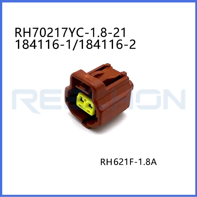
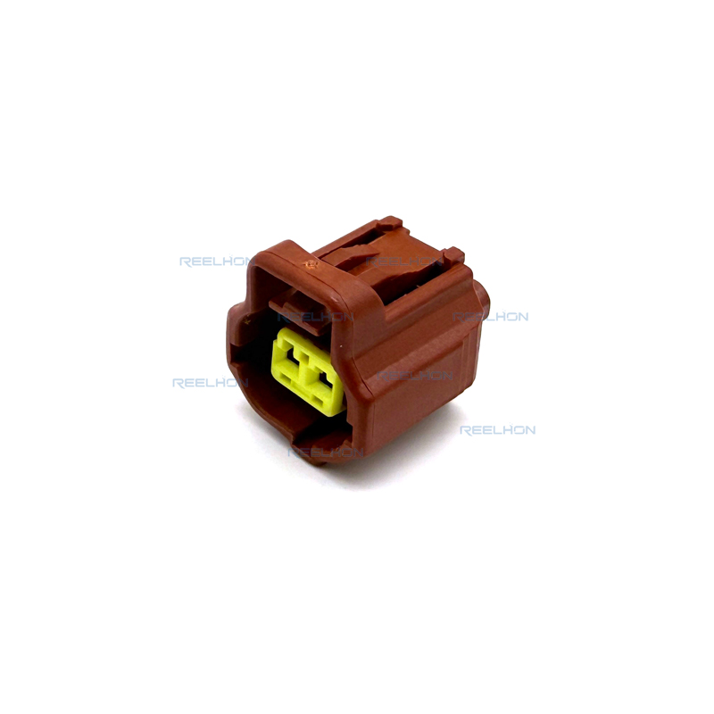
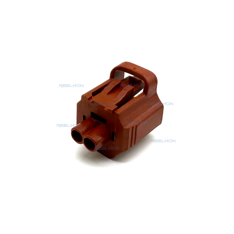
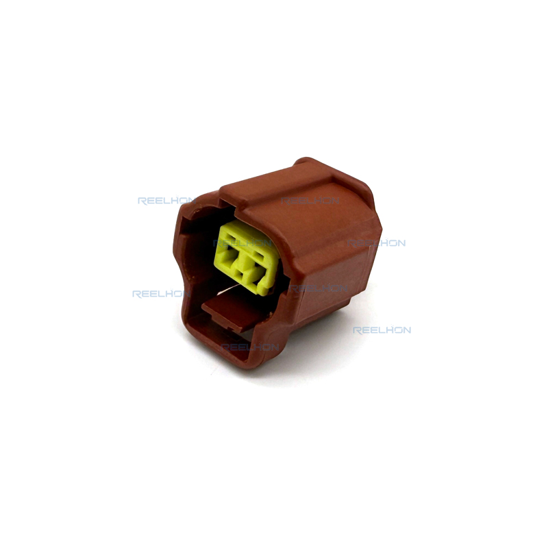
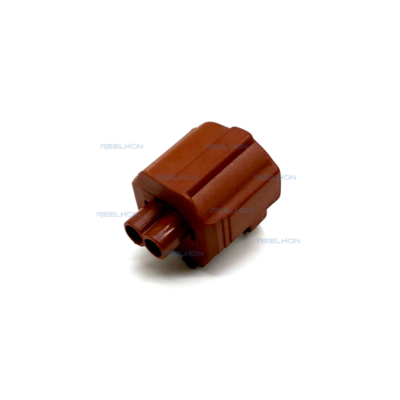
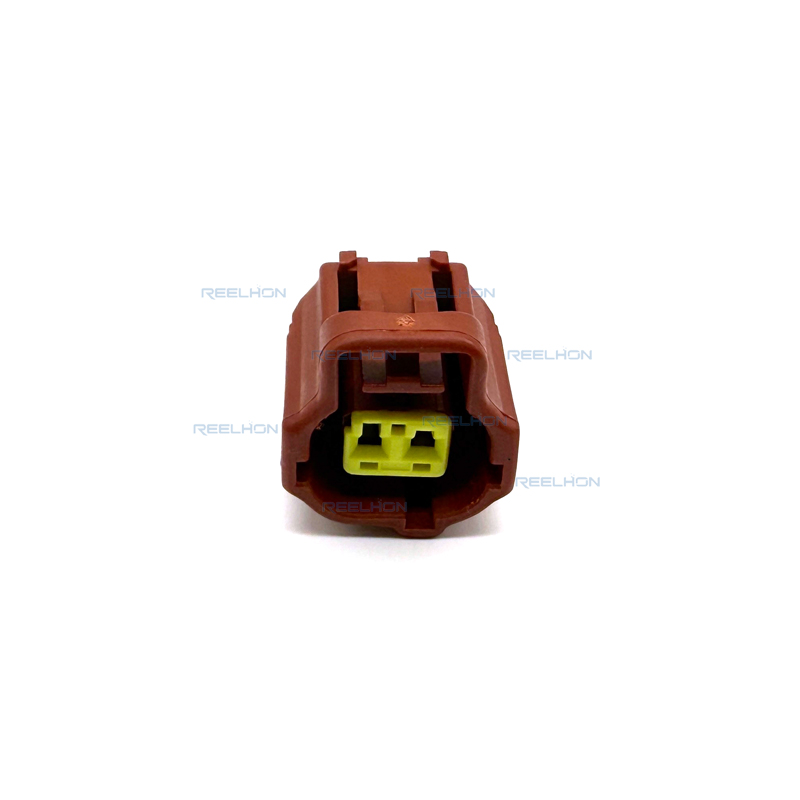
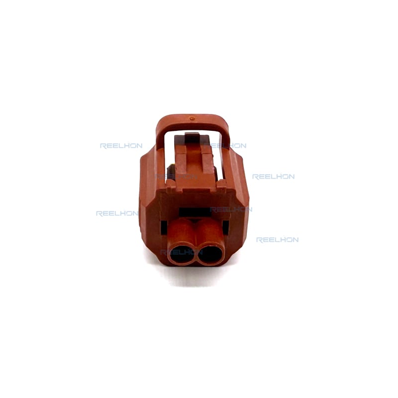
TE Internal Part Number:184116-1
TE Internal Description: 2 POS. PLUG ASSY, KEY H 1/2
Connector & Housing Type: Plug
Number of Positions: 2
Sealable: Yes
Primary Product Color: Not specified (black typical for SSC)
Keying Configuration: H
Housing Material :Glass-filled PBT (class 3) or glass-filled nylon (class 4)
Wire Size Range :22 – 14 AWG (0.30 mm² – 2.0 mm²)
Operating Temperature Range: -40°C to 150°C [-40°F to 302°F]
Connector System: Wire-to-Wire, Sealed
Mounting Type: Cable Mount (Free-Hanging)
The TE Connectivity 184116-1 is a 2-position, sealed plug assembly from the Sealed Sensor Connector (SSC) series. This connector family is designed to accept a wire size range of 22 through 14 AWG and is available in 1, 2, 3, 4, 6, and 12 positions. The 184116-1 specifically offers 2 positions with keying configuration H. The connector is fully sealable, providing waterproof performance for severe environmental conditions and high temperature applications ranging from -40°C to 150°C.
Wire sealing is achieved by means of an individual wire seal which is inserted on the wire and crimped in the insulation support of the contact simultaneously with the contact. Interfacial sealing is achieved with a pre-assembled seal ring located in the plug assembly. When mating, the SSC housing provides an audible "click" to indicate proper connector mating. The housing material is glass-filled polyethylene terephthalate (PBT) for class 3 applications, or glass-filled nylon for class 4 applications.
The Sealed Sensor Connector system offers up to 12 different keying configurations to prevent mis-mating of connectors. The 184116-1 is specified with key H. Optional colors are available for additional keying configurations, though the standard color for this part is not specified in the provided material. The housing latch will lock and a tactile and audible click will be heard when the plug and cap housing have reached the fully mated position. An optional Connector Position Assurance (CPA) tab is available on certain plug assemblies (3-position, 4-position in-line, and 4-position matrix), but is not specified for this 2-position version.
For applications requiring strain relief, wires can be bundled together with cable ties and secured with fixed clamps. The wires must not be confined in any way that would restrict floating action of the contact in the housing. Normally, individual wires should be dressed to a bend radius of at least ten times the insulation diameter. Optional harness retainer clips are available to secure the harness to the chassis or device by sliding the retainer into the slot in the cap housing until it locks into place with a tactile and audible click.
The receptacle contact design will accept stranded conductors and include configurations to cover the full wire size range of 22 through 14 AWG (0.30 mm² to 2.0 mm²). The appropriate size wire seal must be selected which will accommodate the insulation diameter of the wire being used. The wire seal must be placed on the end of the wire prior to termination. The wire must be stripped to the dimensions shown in Figure 2 of specification 114-8004. Do not nick, scrape, or cut the wire conductor during the stripping operation. Do not damage the wire seal when placing it over the wire.
The contact must be located in the appropriate tooling according to the instructions packaged with that tooling. The wire seal shall NOT be cut or broken during the crimping operation, nor shall the insulation or wire seal be crimped into the contact wire barrel. Reasonable care should be taken by tooling operators to provide undamaged wire terminations. Periodic inspections must be made to ensure crimped contact formation is consistent.
Crimp Height: The crimp applied to the wire portion of the contact is the most compressed area and is most critical in ensuring optimum electrical and mechanical performance of the crimped contact. The crimp height must be within the functional range dimensions provided in Figure 2 of the specification.
Crimp Length: For optimum crimp effectiveness, the crimp must be within the area shown in Figure 3. Effective crimp length shall be defined as that portion of the wire barrel, excluding bellmouth(s), fully formed by the crimping tool.
Bellmouths: Front and rear bellmouths shall be evident. Front bellmouth maximum 0.5 mm. Rear bellmouth 0.2 – 0.9 mm.
Cutoff Tab: The cutoff tab must be visible. Maximum cutoff tab length 0.5 mm.
Burrs: The cutoff burr shall not exceed 0.08 mm.
Wire Barrel Flash: The wire barrel flash shall not exceed 0.25 mm.
Wire Location: After crimping, the wire conductor and insulation must be visible in the transition area between the wire and insulation barrels.
Conductor Location: The conductor may extend beyond the wire barrel to a maximum of 1.5 mm.
Wire Seal Location: The wire seal may not extend beyond the specified dimensions.
Wire Barrel Seam: The wire barrel seam must be closed with no evidence of loose wire strands visible in the seam.
Twist and Roll: The twist and roll shall be no more than shown in Figure 4 of the specification. There shall be no deformation or other damage to the mating portion of the crimped contact that will prevent proper mating.
Straightness: The force applied during crimping may cause some bending between the crimped wire barrel and the mating portion of the contact. Such deformation is acceptable within limits. The crimped contact, including cutoff tab and burr, shall not be bent above or below the datum line more than the amount shown in Figure 5. The side-to-side bending of the contact may not exceed the limits provided in Figure 6.
Crimped receptacle contacts should hold the wire firmly and have a pull-test tensile value meeting the specifications in Figure 7 of specification 114-8004. For 22 AWG (0.35 mm²), minimum force is 57 Newtons (13 pounds). For 20 AWG (0.50-0.60 mm²), minimum is 80 Newtons (18 pounds). For 18 AWG (0.75-0.80 mm²), minimum is 106 Newtons (24 pounds). For 16 AWG (1.00-1.20 mm²), minimum is 123 Newtons (28 pounds). For 14 AWG (2.00 mm²), minimum is 178 Newtons (40 pounds). Adjust tensile testing machine for head travel of 25.4 mm per minute and directly and gradually apply force for 1 minute.
Before insertion of the crimped receptacle, the lock plate must be in a pre-staged position. Holding the terminated receptacle contact with the wire barrel seam facing toward the latch on the housing, insert the crimped receptacle into the plug assembly. A click will be heard when the crimped receptacle is fully inserted. After the crimped receptacles have been inserted, press the lock plate into the plug assembly to lock the crimped receptacles into the plug housing. A click will be heard when the lock plate is fully engaged. If there is difficulty in inserting the lock plate, check the crimped receptacle to ensure full insertion.
To disengage the lock plate from the plug housing, insert a jeweler's number 2 screwdriver into the slit between the marked position of the lock plate and plug assembly wall, then lift up the lock plate until it is unlocked. To extract the receptacle contact from the plug housing, while holding the plug housing, push the receptacle contact forward. Insert a jeweler's number 2 screwdriver between the contact latch and the receptacle assembly, lift the contact latch, and pull the wire and receptacle contact out of the housing. Do NOT insert the screwdriver into the mating end of the receptacle contact as damage may occur.
In order to maintain a water-tight connector system, optional cavity plugs must be used to seal all unused circuits. Insert the cavity plug from the wiring side of the connector housing until it is fully seated.
A damaged contact can be removed and replaced with a new one. All contacts must be removed from a damaged connector housing and the housing replaced with a new one.
Hand tools that accommodate the full wire size range are designed for prototype and low-volume applications, such as repair of damaged contacts. Applicators are designed for the full wire size range of strip-fed, precision formed contacts, and provide for high volume, heavy duty production requirements. The applicators can be used in bench or floor model power units. Hand tool 411-5322 (Double Action Hand Tool) is available for Sealed Sensor Connectors. Applicator 408-8040 (Heavy Duty Miniature Quick Change Applicators) is recommended. Power units include AMP-O-LECTRIC Model G (354500-[]) and Entry Level Terminator (1338600-[]).
Based on the TE Connectivity declaration provided for part number 184116-1: EU RoHS (2011/65/EU) – Compliant, including Delegated Directive 2015/863/EU. EU ELV Directive 2000/53/EC – Compliant. China RoHS 2 – No restricted substance(s) above threshold. EU REACH Regulation (EC) No. 1907/2006 – Does not contain REACH SVHC. ECHA Candidate List: February 2026 (253 substances declared). Halogen Content: Not low halogen – contains Br or Cl > 900 ppm, but BFR/CFR/PVC-free. Solder Process Capability: Not suitable for soldering processes.
The TE 184116-1 is a 2-position sealed sensor plug assembly with keying configuration H. Designed for wire sizes 22 through 14 AWG and operating temperatures from -40°C to 150°C, this connector provides reliable sealed connections for automotive and industrial applications. When crimped according to the Sealed Sensor Connector application specification using approved tooling, and with proper wire seal selection and cavity plugs for unused circuits, the system maintains water-tight integrity and meets applicable environmental compliance standards including RoHS, ELV, and REACH SVHC-free requirements.
| Product Type Features | |
| Connector & Housing Type | Plug |
| Sealable | Yes |
| Connector System | Wire-to-Wire |
| Connector and Terminal End To | Wire & Cable |
| Structural Characteristics | |
| Number of Positions | 2 |
| Wire Size Range | 22 – 14 AWG (0.30 mm² – 2.0 mm²) |
| Body Characteristics | |
| Primary Product Color | Not specified |
| Keying Configuration | H |
| Housing Material | Glass-filled PBT (class 3) or glass-filled nylon (class 4) |
| Environmental Characteristics | |
| Operating Temperature Range | -40°C to 150°C [-40°F to 302°F] |
| Mechanical Attachment | |
| Connector Mounting Type | Cable Mount (Free-Hanging) |
| Mating Alignment | Provided (via keying) |
| Mating Fixation Type | Latch |
| Packaging Characteristics | |
| Packaging Method | Not specified |
| Packaging Quantity | Not specified |
| Compliance | |
| EU RoHS (2011/65/EU) | Compliant |
| EU ELV Directive 2000/53/EC | Compliant |
| China RoHS 2 | No Restricted Substance(s) Above Threshold |
| EU REACH (EC) No. 1907/2006 | Does not contain REACH SVHC |
| Halogen Content | Not low halogen (Br or Cl > 900 ppm) – BFR/CFR/PVC-free |
| Solder Process Capability | Not suitable for soldering processes |

Be the first to get our latest styles and offers.
5th Floor, Building 23, Phase 3, Tingtian Micro Park, Ruian City, Wenzhou, Zhejiang Province
Copyright © 2026 Ruian Ruihong Trading Co., Ltd. All rights reserved. - Privacy Policy
 EN
EN