Nominal Voltage Architecture (V): 12
Connector & Housing Type: Automotive Housing for Female Terminals
Number of Positions: 8
Sealable: No
Operating Temperature Range: -40 – 130 °C [-40 – 266 °F]
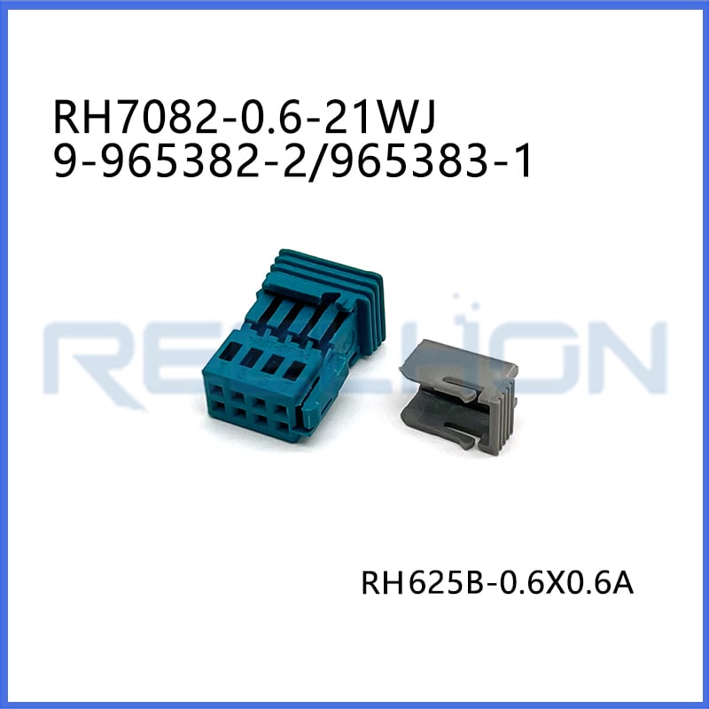
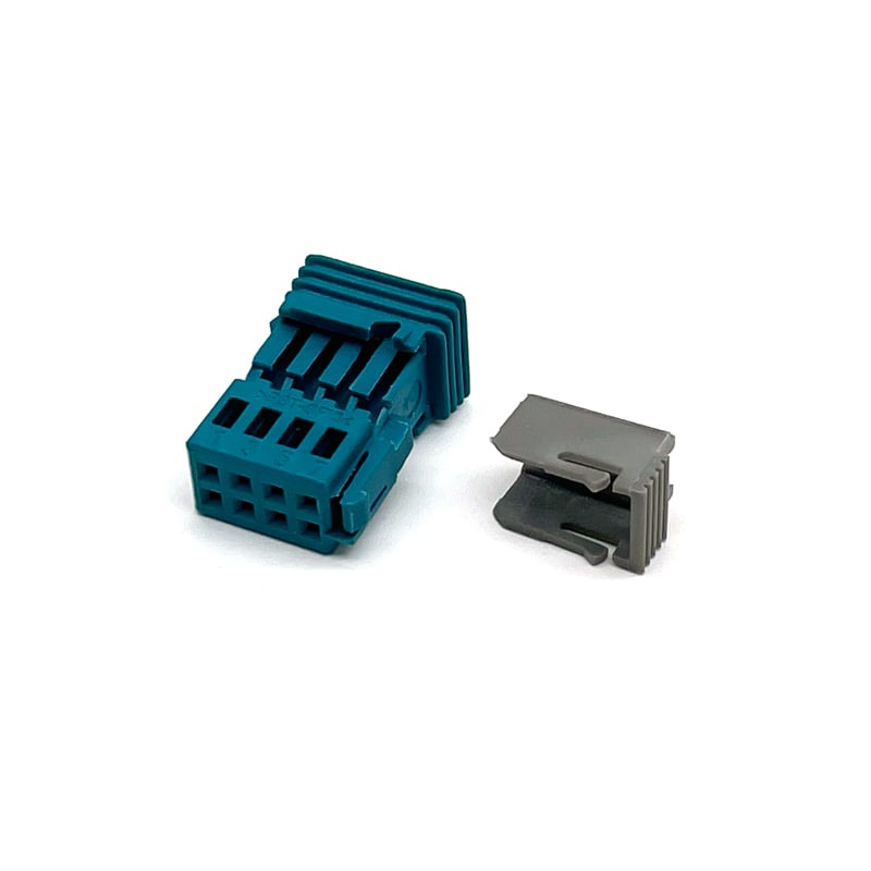
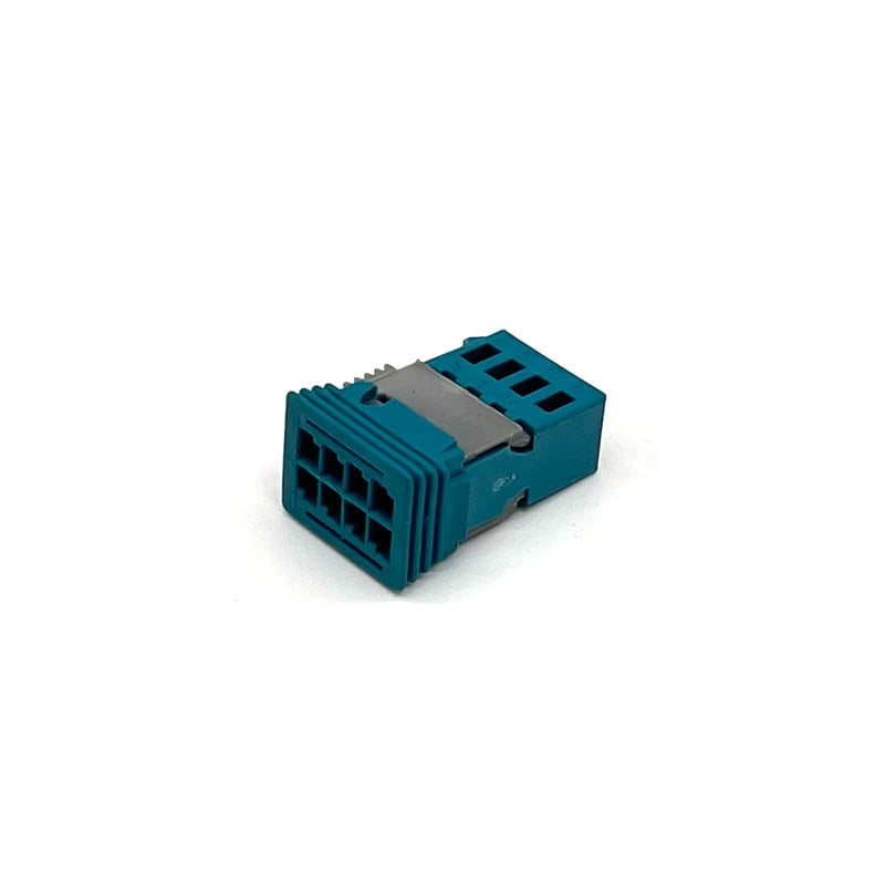
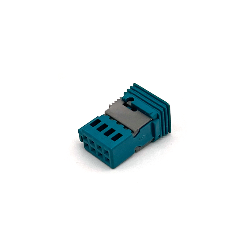
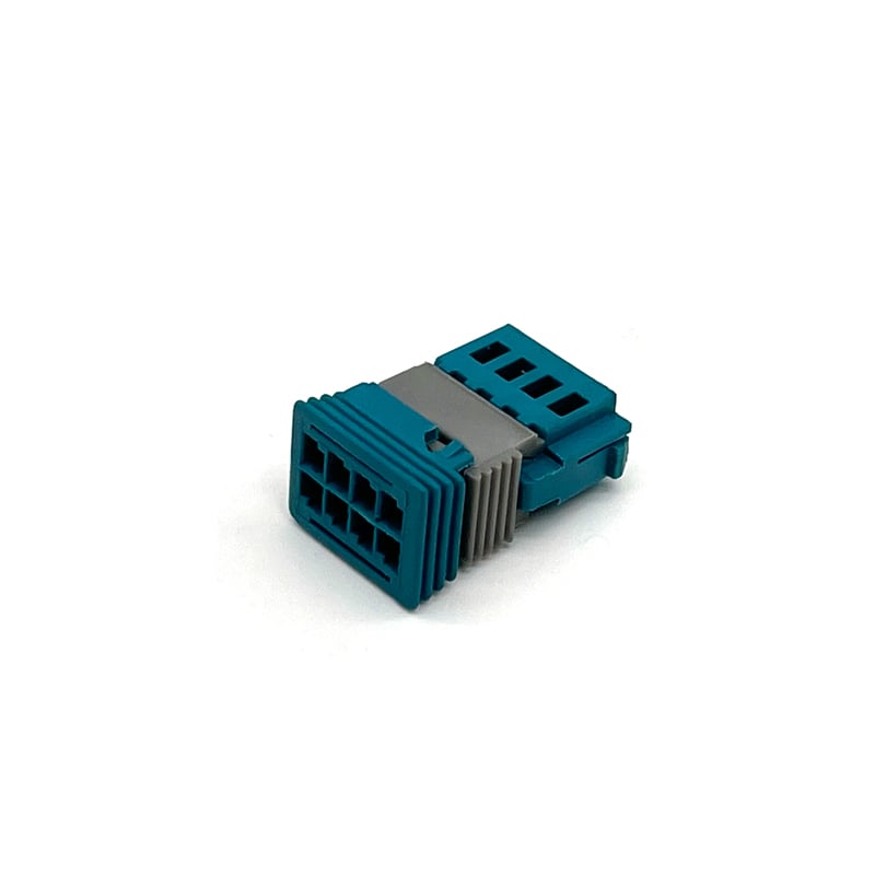
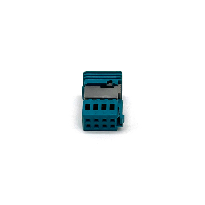
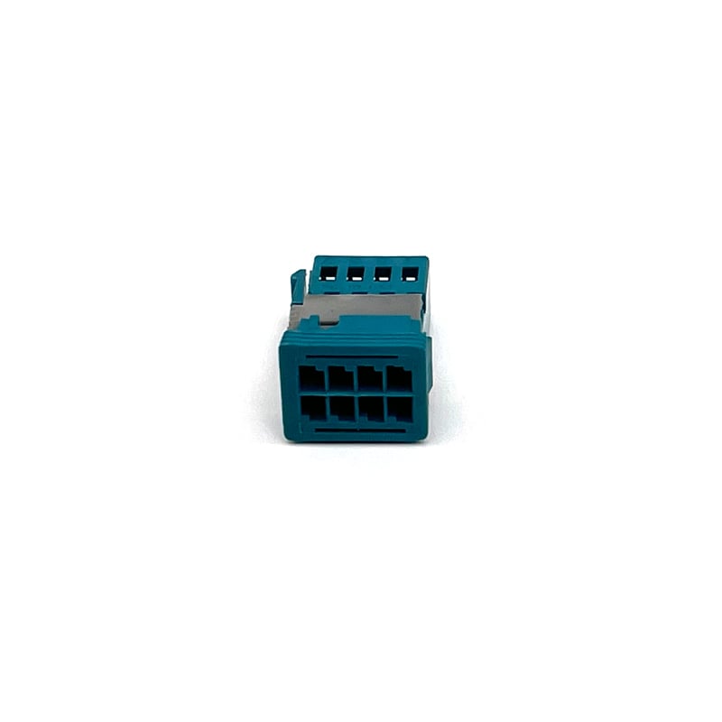
The 8 position receptacle housing is part of the Micro Quadlok System. It is designed to accept up to 8 Micro Quadlok System female contacts arranged in two parallel rows of 4 contacts each. The connector is intended for wire-to-board and wire-to-device connection systems. The housing features a rectangular shape, non-hybrid, and a centerline pitch of 2.54 mm [.1 in]. The connector is for cable mount (free hanging) installation with a 180° wire exit angle. The primary product color is water blue. The housing material is PBT GF15. This housing supports a nominal voltage architecture of 12 V. The overall temperature range is from -40°C to +130°C.
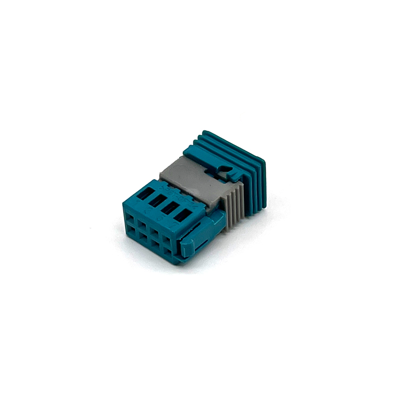
The receptacle housing was developed for outside mirror contacting. The application site is the outside mirror in the passenger car area. The complete 8-pole coupling consists of a receptacle housing as contact carrier and a sliding lock for the secondary contact retention. The sliding lock is delivered as a separate part and is inserted into the receptacle housing after the contacts are loaded. It locks in end position with the housing by two spring hooks. Then the complete coupling is guided through the collar of the outside mirror housing and contacts a header mounted on the printed circuit board. After contacting, the housing is locked to the collar by a one-side integrated spring latch.
The sliding lock forms with its guides the second mechanical contact underreach as secondary contact locking. The secondary contact retention is realized by a slide which locks in end position with the housing. The contacts are held in the housing by the primary locking and the secondary locking. The function of the secondary locking is accomplished by a slide that locks in end position with the housing.
The receptacle housing can be coded. The connector and keying code is Z. Mating alignment is provided with keyed type. Terminal position assurance is not provided. Strain relief is not provided. The connector is not serviceable and does not have connector position assurance.
For the contact system, applicable female terminals are Micro Quadlok System contacts. The terminal size is 0.64mm with a mating tab width of 0.64 mm [.025 in]. The maximum current rating per terminal is 7.5 A. For details on current carrying capability, refer to the product specification of the Micro Quadlok contact system. The minimum transferable current signal per contact pair is also given in that specification. Maximum number of mating cycles is ≤ 10 for tinned contacts.
Electrical characteristics: Voltage proof testing according to DIN/IEC 512 Part 2.4a with test voltage 500V, test duration 2 seconds, connection type C, no flashover or breakdown permitted. Insulation resistance according to DIN/IEC 512 Part 2.3a with test voltage 500V, connection type C, minimum insulation resistance ≥ 1 MΩ.
Mechanical characteristics: Contact retention forces in the housing are measured with a tensile/compression testing machine at speed 25 mm/min. For primary locking (first contact retention, with secondary locking removed), the minimum retention force is ≥ 60 N, tested axially on the wire. For secondary locking (second contact retention), the minimum retention force is ≥ 50 N. Due to space constraints imposed by the customer and the impossibility of mechanical stabilization of the slide for contact securing, the minimum requirements for contact retention forces are reduced.
All tests are performed under general test conditions: number of test specimens ≥ 5 pieces, test specimens must show no visible damage, must correspond to the current drawing status, only series parts are used for test purposes, dynamic loads from wiring harness movement must be kept away from the tab housing and thus from the entire connector, test specimens are tested only in new condition and only at room temperature.
The receptacle housing and the sliding lock are visually, functionally and dimensionally inspected according to quality guidelines. The materials and surface finishes are given in the drawing documents.
Packaging method is Box.
Environmental and regulatory compliance: EU RoHS (2011/65/EU) compliant; EU ELV Directive 2000/53/EC compliant; China RoHS 2: No Restricted Substance(s) Above Threshold; EU REACH Regulation (EC) No. 1907/2006: Does not contain REACH SVHC (ECHA Candidate List February 2026 (253)); Halogen Content: BFR/CFR/PVC free, but Br or Cl from other sources > 900 ppm; Solder Process Capability: Not suitable for soldering process.
The connector is not low halogen – it contains Br or Cl > 900 ppm from other sources although it is BFR/CFR/PVC free.
| Product Type Features | |
| Connector Shape | Rectangular |
| Hybrid Connector | No |
| Connector and Housing Type | Automotive Housing for Female Terminals |
| Sealable | No |
| Primary Locking Feature | Locking Lance |
| Connector System | Wire-to-Board, Wire-to-Device |
| Connector and Terminal End To | Wire and Cable |
| Structural Characteristics | |
| Number of Positions | 8 |
| Number of Rows | 2 |
| Electrical Characteristics | |
| Nominal Voltage Architecture | 12 V |
| Body Characteristics | |
| Wire Exit Angle | 180° |
| Primary Product Color | Water Blue |
| Connector and Keying Code | Z |
| Contact Characteristics | |
| Terminal Type | Female |
| Terminal Size | 0.64mm |
| Mating Tab Width | 0.64 mm [.025 in] |
| Maximum Terminal Current Rating | 7.5 A |
| Mechanical Attachment | |
| Mating Alignment | Provided |
| Mating Alignment Type | Keyed |
| Terminal Position Assurance | No |
| Strain Relief | Not provided |
| Connector Mounting Type | Cable Mount (Free Hanging) |
| Housing Characteristics | |
| Housing Material | PBT GF15 |
| Centerline (Pitch) | 2.54 mm [.1 in] |
| Dimensions | |
| Connector Height | 10.2 mm [.402 in] |
| Product Length | 13.4 mm [.528 in] |
| Row-to-Row Spacing | 2.54 mm [.1 in] |
| Product Width | 20 mm [.787 in] |
| Environmental | |
| Operating Temperature Range | -40 – 130 °C [-40 – 266 °F] |
| Maximum Operating Temperature | 130 °C [266 °F] |
| Operation/Application | |
| Circuit Application | Signal |
| Packaging Characteristics | |
| Packaging Method | Box |
| Other | |
| Serviceable | No |
| Connector Position Assurance | No |
| Compliance | |
| EU RoHS (2011/65/EU) | Compliant |
| EU ELV Directive 2000/53/EC | Compliant |
| China RoHS 2 | No Restricted Substance(s) Above Threshold |
| EU REACH (EC) No. 1907/2006 | Does not contain REACH SVHC |
| Halogen Content | BFR/CFR/PVC free, Br or Cl > 900 ppm from other sources |
| Solder Process Capability | Not suitable for soldering process |

Be the first to get our latest styles and offers.
5th Floor, Building 23, Phase 3, Tingtian Micro Park, Ruian City, Wenzhou, Zhejiang Province
Copyright © 2026 Ruian Ruihong Trading Co., Ltd. All rights reserved. - Privacy Policy
 EN
EN