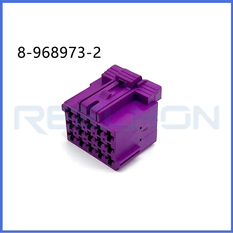
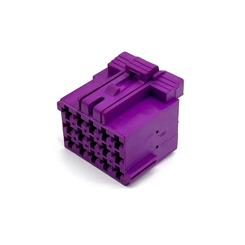
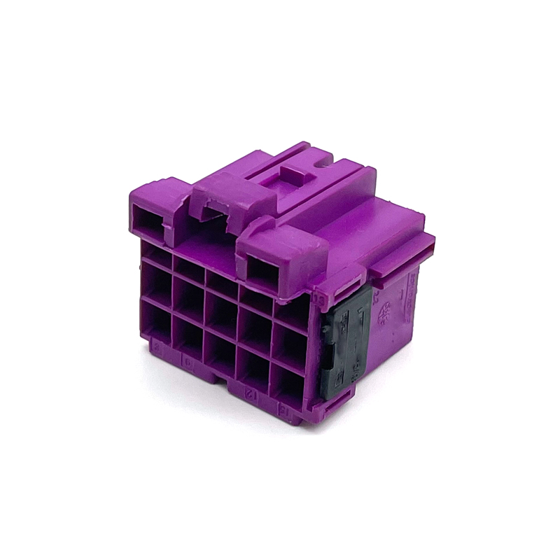
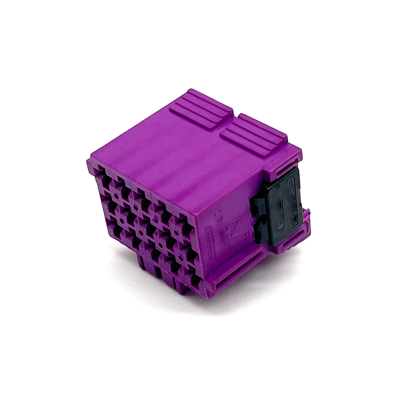
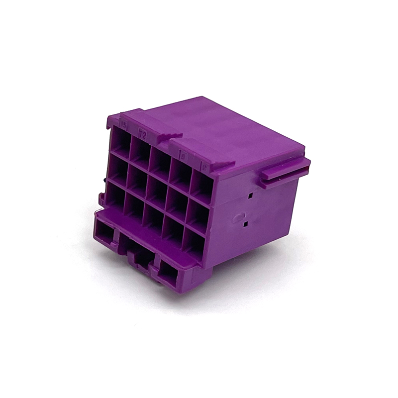
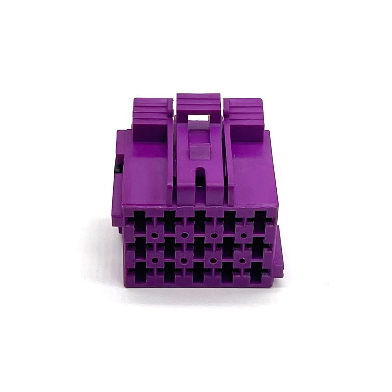
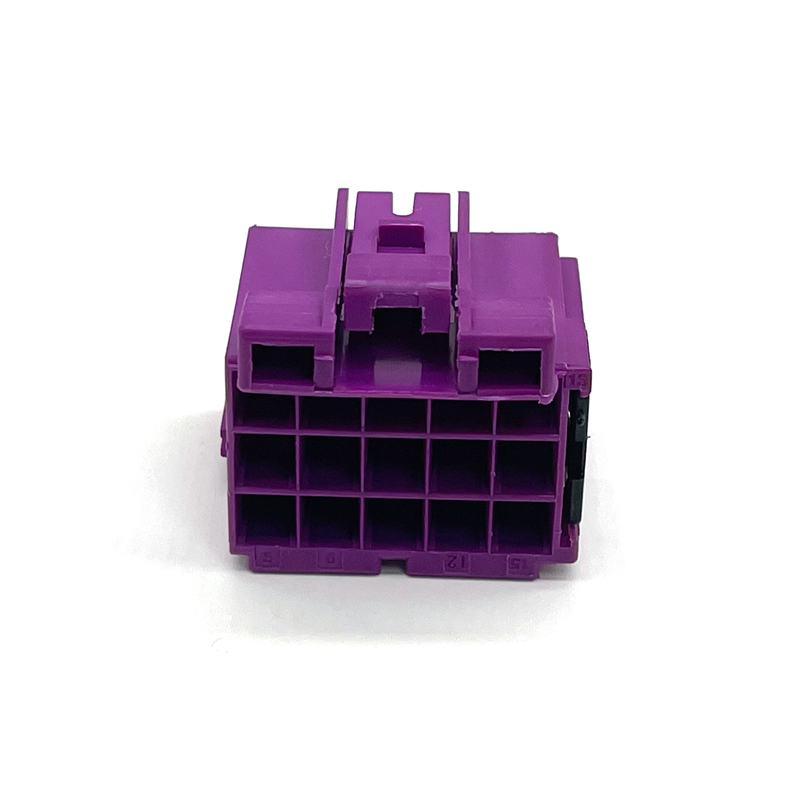
TE Internal Part Number:8-968973-2
TE Internal Description:MCP2.8 GEH ASSY 15P
Connector & Housing Type:Housing for Female Terminals
Number of Positions:15
Number of Rows:3
Sealable:No
Primary Product Color:Gray
Connector & Key Code: A
Terminal Type: Female
Terminal Size:2.8 mm
Mating Tab Width:2.8 mm [0.11 in]
Centerline (Pitch) :5 mm [0.197 in]
Mounting Type:Cable Mount (Free-Hanging)
Housing Material:Glass filled PBT
Operating Temperature Range: -40 – 120 °C [-40 – 248 °F]
Nominal Voltage Architecture:12 V, 24 V
Wire Size Range:Max. 2.5 mm² FLR (refer to AMP MCP 2.8 contact application specification 114-18148-0)
Packaging Method:Carton
Packaging Quantity:1200
The TE Connectivity 8-968973-2 is a 15-position, 3-row, unsealed female housing from the AMP MCP 2.8 connector family. This housing is designed for wire-to-wire and wire-to-board applications, accepting AMP MCP 2.8 female terminals. The connector is non-sealable and intended for use in environments where fluid ingress protection is not required. The housing is molded in gray glass-filled PBT (polybutylene terephthalate), providing mechanical strength and thermal stability. The nominal voltage architecture supports 12 V and 24 V systems, with a working voltage of 28 V DC. The operating temperature range of the housing is from -40 °C to 120 °C. The centreline pitch between circuits is 5 mm [0.197 in], and the row-to-row spacing is 5.5 mm [0.217 in].
This product is part of the AMP MCP 2.8 unsealed connector system, which includes socket housings (female housings), tab housings (male housings), and tab headers (pin headers for PCB mounting). The 8-968973-2 is the socket housing that can mate with a corresponding tab housing (wire-to-wire) or a tab header (wire-to-board), such as the 15-position pin header shown in product specification 108-94624 (drawing number 966140 series). The housing features a primary locking mechanism on the terminal. A secondary locking device (terminal position assurance) is provided and delivered in the pre-locked position. The connector also includes keying and polarization features (code A, gray color) to prevent mismating. The housing is designed for cable mounting (free-hanging) with a straight 180° wire exit angle. The product is not serviceable (repairable = No) and does not include a connector position assurance feature.
The housing is made from glass-filled PBT, a thermoplastic material that offers good dimensional stability, heat resistance, and mechanical robustness. The material is low halogen, with Br, Cl, and F each below 900 ppm per homogeneous material, and is also BFR/CFR/PVC-free. The terminal contacts (not supplied with the housing) are made from copper alloy and are tin-plated as standard for the AMP MCP 2.8 system, with a durability of ≤10 mating cycles for tinned contact surfaces. Since the connector is unsealed, there are no wire seals or peripheral seals. Unused cavities do not require sealing plugs because the connector is not required to be watertight. The housing color is gray, and the keying code is A, which ensures correct polarization when mating with the corresponding counterpart. The secondary locking device is made of plastic and is an integral part of the socket housing.
The 8-968973-2 accepts AMP MCP 2.8 female terminals (receptacle contacts). According to application specification 114-94624, the maximal permitted wire size for the AMP MCP 2.8 contact system is 2.5 mm² FLR. For detailed information on the contact system, refer to customer drawing 1355036, product specification 108-18513-0, and application specification 114-18148-0. The contacts are crimped to the wires using approved tooling, and then inserted into the housing cavities. The housing has a primary retention lance that locks the contact in place. In addition, a secondary locking device provides an additional retaining force for the terminals if the primary lock fails. The secondary locking device is delivered in the pre-locked position, and contacts can only be inserted when the secondary locking device is in this pre-locked position. After all contacts are loaded, the secondary locking device must be moved manually into the final locked position. Reaching the correctly locked position is signaled by an audible click.
Based on the product specification for the mating tab header (108-94624) which shares the same AMP MCP 2.8 contact system, the connector assembly is designed to meet the following electrical requirements. The voltage proof test requires no flash-over or breakdown between adjacent contacts and the outer contour when tested with 500 Veff at 50 Hz for 60 seconds, according to IEC 60512-2 test 4a method C. The insulation resistance shall be a minimum of 10 MΩ when measured with 500 V DC according to IEC 60512-2 test 3a method C. The overall resistance across the mated contact and terminal (through-resistance) shall not exceed 6 mΩ in the new state, measured according to IEC 60512-2 test 2a.
The mechanical performance of the connector system is defined in product specification 108-94624 for the tab header, and the socket housing is designed to meet equivalent requirements. The mating and unmating force of the connector assembly (when the female housing is mated with the corresponding tab header or tab housing) is specified as a maximum of 15 N per number of ways. For a 15-position connector, the maximum mating force is 225 N, and the maximum unmating force is also 225 N. The test is performed according to IEC 60512-7 test 13a with an actuating speed of 25 mm/min. The contact retention force for the tabs in the header (and by extension the retention of the female terminals in the socket housing) is a minimum of 50 N in the mating direction, tested according to IEC 60512-8 test 15a at a speed of 25 mm/min. The steady state carrying capacity of the connection locking (the latch strength) shall withstand a minimum of 100 N in the pull-off direction, tested according to DIN EN 60512-15-6 at a speed of 25 mm/min. These mechanical requirements ensure reliable mating, unmating, and locking under typical automotive conditions.
The socket housing is delivered with the secondary locking device in the pre-locked position. To load contacts, first ensure the secondary locking is in pre-locked position. Then insert the crimped AMP MCP 2.8 female terminal into the desired cavity from the rear (wire side) with correct orientation. Correct orientation is shown in Figure 3.1.1.1 of application specification 114-94624. If the orientation is incorrect, the contact cannot be fully inserted and the crimp area will protrude from the housing; the contact must then be turned by 90°. When orientation is correct, the primary locking lance will engage with an audible click, and the contact will be completely inside the cavity. After all contacts are inserted, the secondary locking device must be pushed manually into the final locked position (see Figure 3.2.1.1 of the application specification). An audible click indicates that the fully locked position is reached. Note that the secondary locking device does not stringently detect the correct position of the terminal in the cavity; correct contact location must be assured before the secondary locking device is activated. If the secondary locking device is not in the locked position, the connectors cannot be mated with normal force (Poka-Yoke feature). To unlock the secondary locking device for contact extraction, a suitable ballpoint pen or similar tool must be inserted into the provided recess to move the locking device back to the pre-locked position.
To extract contacts from the socket housing, the secondary locking device must first be moved to the pre-locked position. Then, the blades of an extracting tool (details are given in the contact application specification) must be inserted from the mating side into the two slots of the contact cavity until they stop; this unlocks the contact. The tool remains in position, and the contact can then be extracted by pulling on the cable. Do not pull the cable before unlocking the contact. By gently pushing the cable against the cable release direction, the unlocking procedure becomes easier because the contact lances are not restricted by the housing.
The connectors described in this specification are equipped with two protection features: coding and polarization, and position control of the secondary locking device. Correct polarization and coding must be chosen for the counterpart. Each connector group has its own individual polarization elements for each number of ways, so it is not possible to mate a 15-position socket housing into a tab housing or tab header of a different position size. Coding (A/B/C/D/E/F) is visible by color and physical by coding ribs. If the secondary locking device is not in the locked position, the connectors cannot be mated with regular force. Only when the secondary locking device is completely locked can mating be performed. To mate, align the keying features and push until the locking hook of the socket housing engages with the counterpart. A mechanical stop and a soft click indicate that the locked position is reached. To unmate, press the locking hook of the socket housing until it touches the housing, then pull the connectors apart with some strength. Connector mating and unmating under load is not permitted.
The operating temperature range for the 8-968973-2 housing is -40 °C to 120 °C. This is broader than the -30 °C to 100 °C range specified for the standard unsealed MCP 2.8 pin headers in product specification 108-94624. The housing material is suitable for this extended range, and the connector is intended for use in automotive underhood and interior applications where temperatures are elevated but environmental sealing is not necessary. The product is not rated for IP protection because it is unsealed.
The socket housing is delivered as bulk packaged and shipped in a corrugated box (carton). The packaging quantity is 1200 pieces. The secondary locking device of the housing is delivered in the pre-locked position. However, due to bulk packaging, some housings may be received with the secondary locking device not in the pre-locked position; this does not constitute a defect. In such cases, the secondary locking device should be relocated into the pre-locked position as described in the application specification. Streaks, brush marks, or slight dents on the surface caused by bulk packaging do not affect the usability or function of the components. Non-attached locking hooks at the socket housings are also not deemed a fault. If the corner surfaces of the socket housing are broken, reconsignment is requested for replacement.
Based on the information provided for part number 8-968973-2, the product is compliant with EU RoHS (2011/65/EU) including Delegated Directive 2015/863/EU. It is also compliant with EU ELV Directive 2000/53/EC. Under China RoHS 2, there are no restricted substances above the threshold. Regarding EU REACH Regulation (EC) No. 1907/2006, the product does not contain any Substance of Very High Concern (SVHC) as per the ECHA Candidate List updated February 2026 (253 substances). The halogen content is low: each homogeneous material contains Br, Cl, and F below 900 ppm, and the product is also BFR/CFR/PVC-free. The solder process capability is not suitable for soldering processes, as this is a crimp connector housing.
The TE Connectivity 8-968973-2 is a 15-position, 3-row, unsealed female housing for the AMP MCP 2.8 wire-to-wire and wire-to-board connector system. It is molded in gray glass-filled PBT, rated for 12 V and 24 V nominal voltage (28 V DC working), and operates from -40 °C to 120 °C. The housing accepts AMP MCP 2.8 female terminals for wire sizes up to 2.5 mm², features a 5 mm pitch, and is free-hanging with a 180° wire exit. It includes a secondary locking device (terminal position assurance) that must be moved to the final locked position after contact insertion. The connector is compliant with RoHS, ELV, REACH SVHC-free, and low halogen requirements. When mated with the corresponding tab housing or tab header, the connector system meets electrical requirements of 500 V dielectric strength, 10 MΩ insulation resistance, and 6 mΩ contact resistance, as well as mechanical requirements of 15 N per way mating force, 50 N contact retention, and 100 N latch strength. This connector is suitable for automotive power applications where environmental sealing is not required, providing reliable electrical and mechanical performance in accordance with TE specifications.
| Product Type Features | |
| Connector & Housing Type | Housing for Female Terminals |
| Connector Shape | Rectangular |
| Hybrid Connector | No |
| Sealable | No |
| Primary Locking Feature | On Terminal |
| Connector System | Wire-to-Board, Wire-to-Wire |
| Connector and Terminal End To | Wire & Cable |
| Structural Characteristics | |
| Number of Positions | 15 |
| Number of Rows | 3 |
| Electrical Characteristics | |
| Operating Voltage (VDC) | 28 V |
| Nominal Voltage Architecture | 12 V, 24 V |
| Circuit Application | Power (typical) |
| Body Characteristics | |
| Wire Exit Angle | 180° |
| Primary Product Color | Gray |
| Connector & Key Code | A |
| Housing Material | Glass filled PBT |
| Centerline (Pitch) | 5 mm [0.197 in] |
| Contact Characteristics | |
| Terminal Type | Female |
| Terminal Size | 2.8 mm |
| Mating Tab Width | 2.8 mm [0.11 in] |
| Mechanical Attachment | |
| Mating Alignment | Provided |
| Mating Alignment Type | Keyed |
| Terminal Position Assurance | Yes (secondary locking device) |
| Stress Relief | Not provided |
| Connector Mounting Type | Cable Mount (Free-Hanging) |
| Dimensions | |
| Connector Height | 24 mm [0.945 in] |
| Product Length | 31 mm [1.22 in] |
| Product Width | 31 mm [1.22 in] |
| Row-to-Row Spacing | 5.5 mm [0.217 in] |
| Environmental Characteristics | |
| Operating Temperature Range | -40 – 120 °C [-40 – 248 °F] |
| Maximum Operating Temperature | 120 °C [248 °F] |
| Packaging Characteristics | |
| Packaging Method | Carton |
| Packaging Quantity | 1200 |
| Other | |
| Serviceable | No |
| Connector Position Assurance | No |
| Compliance | |
| EU RoHS (2011/65/EU) | Compliant |
| EU ELV Directive 2000/53/EC | Compliant |
| China RoHS 2 | No Restricted Substance(s) Above Threshold |
| EU REACH (EC) No. 1907/2006 | Does not contain REACH SVHC |
| Halogen Content | Low halogen (Br, Cl, F < 900 ppm per homogeneous material); BFR/CFR/PVC-free |
| Solder Process Capability | Not suitable for soldering processes |

Be the first to get our latest styles and offers.
5th Floor, Building 23, Phase 3, Tingtian Micro Park, Ruian City, Wenzhou, Zhejiang Province
Copyright © 2026 Ruian Ruihong Trading Co., Ltd. All rights reserved. - Privacy Policy
 EN
EN