
 EN
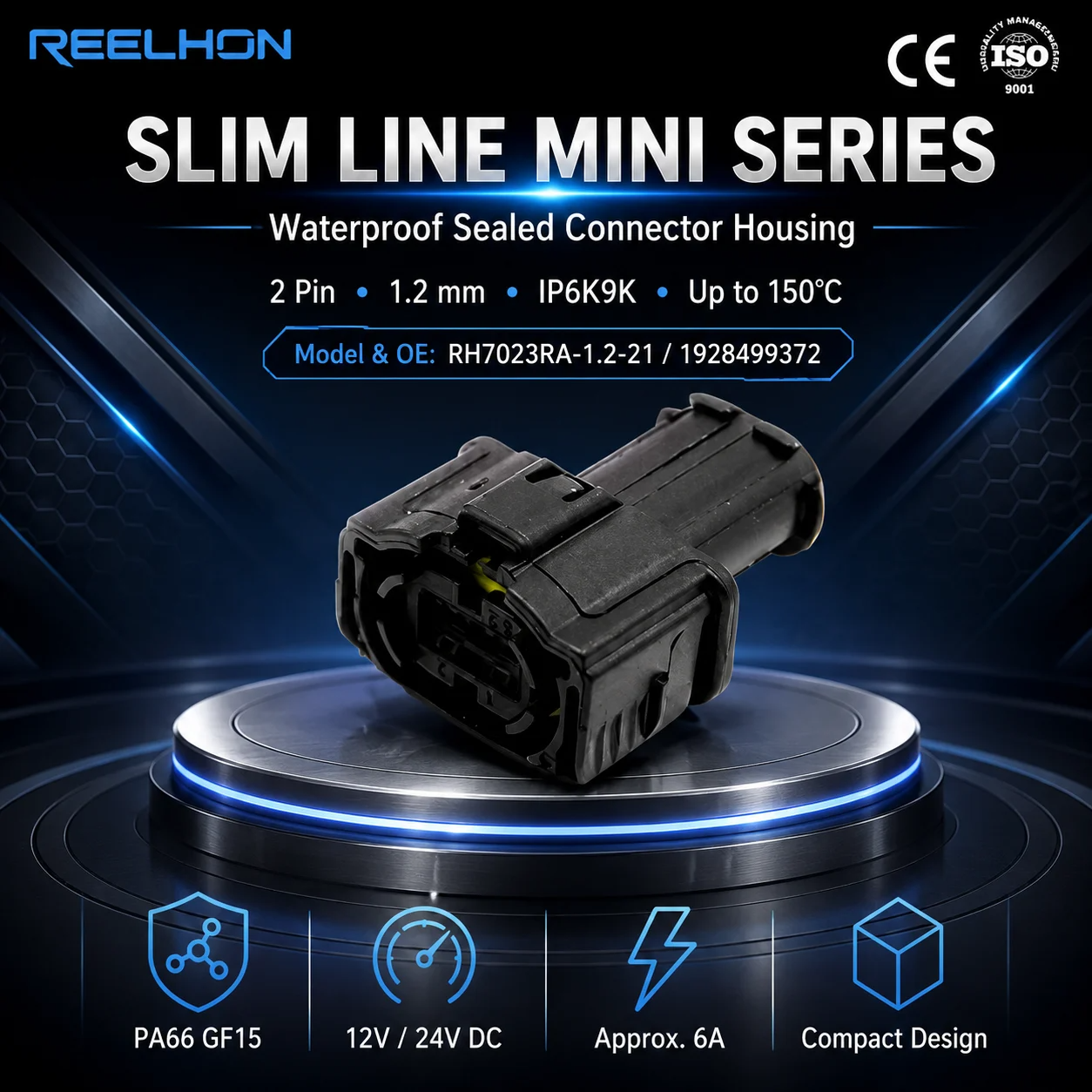
A reliable 2 pin connector is one of the most fundamental components in any electrical wiring system, yet achieving stable contact resistance in every single unit demands rigorous manufacturing discipline. Whether deployed in automotive wiring harnesses, industrial control panels, or consumer electronics, a 2 pin connector must deliver consistent electrical performance across thousands of mating cycles and a wide range of environmental conditions. The challenge facing every factory is not simply producing a 2 pin connector that works — it is producing one that works predictably, every time, at scale.
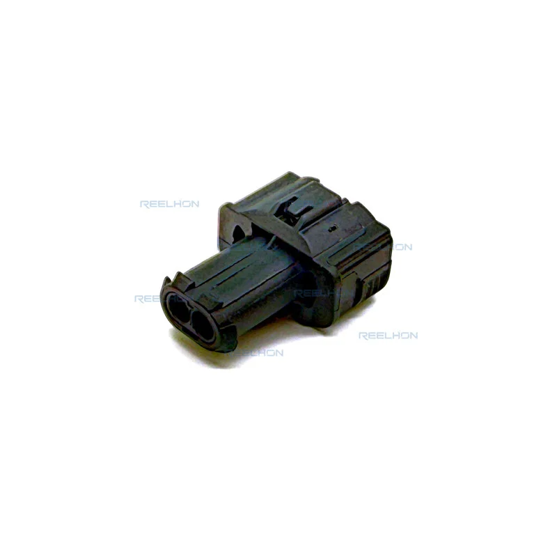
Electrical contact resistance is the measure of opposition a 2 pin connector introduces at the point where two conductive surfaces meet. When contact resistance is too high or unstable, circuits experience voltage drops, heat buildup, and signal interruption — all serious failures in critical applications. Understanding how factories engineer and control this parameter reveals why the quality of a 2 pin connector cannot be taken for granted, and why manufacturing process decisions matter as much as material choices.
Material Selection and Terminal Engineering for a 2 Pin Connector
Conductive Metal Choices That Define Performance
The electrical contact resistance of any 2 pin connector begins with the base metal selected for its terminals. Copper alloys — particularly brass and phosphor bronze — dominate because they offer an excellent balance of electrical conductivity, mechanical spring force, and formability. A 2 pin connector terminal made from high-grade copper alloy maintains its clamping force even after repeated mating cycles, which directly prevents contact resistance from rising over the product's service life. Factories that source premium copper alloys invest in consistent raw material certification to eliminate batch-to-batch variation that could affect the performance of every 2 pin connector produced.
Plating Processes That Protect the Contact Interface
Surface plating is critical to keeping contact resistance low in a 2 pin connector. Gold plating is used in signal-sensitive applications because gold resists oxidation completely, preserving the pristine metal-to-metal contact that defines low-resistance performance. For higher-current 2 pin connector designs, tin or tin-lead plating is more economical while still providing effective oxidation protection. Factories control plating thickness with tight tolerances — typically measured in microinches — because under-plated terminals on a 2 pin connector oxidize prematurely, while over-plating wastes material and can cause dimensional issues during mating. The uniformity of the plating layer across every 2 pin connector terminal is verified through X-ray fluorescence testing at defined production intervals.
Precision Tooling and Dimensional Control in 2 Pin Connector Manufacturing
Stamping Accuracy and Terminal Geometry
The geometry of the contact interface is the most direct mechanical factor affecting a 2 pin connector's electrical resistance. During stamping, factories produce terminal blanks with exacting dimensional tolerances, because even slight variations in contact arm width or spring beam angle alter the normal force applied between mating terminals. A 2 pin connector with insufficient normal force will exhibit high or unstable contact resistance, especially under vibration. High-precision progressive stamping dies, maintained and recalibrated on strict schedules, ensure every 2 pin connector terminal leaves production within the designed tolerance band. Factories measure critical terminal dimensions using optical comparators and coordinate measuring machines to catch tool wear before it degrades 2 pin connector quality.
Housing Dimensions and Mating Alignment
Even a perfectly engineered terminal will underperform if the 2 pin connector housing does not position it correctly during mating. Injection-molded housings must hold terminals in precise axial alignment so that contact surfaces engage squarely rather than at an angle. Misalignment in a 2 pin connector housing increases localized contact stress, damages plating surfaces, and elevates resistance unpredictably. Factories use first-article inspection protocols and ongoing statistical process control to validate that every 2 pin connector housing meets dimensional specifications. The mating force profile of a 2 pin connector is tested during development to confirm that insertion and withdrawal forces remain within the range that ensures full terminal engagement without overstressing the housing structure.
Quality Testing and Validation Protocols for the 2 Pin Connector
Electrical Contact Resistance Testing Methods
Factories validate 2 pin connector contact resistance using the four-wire Kelvin measurement method, which eliminates lead resistance from the reading and provides an accurate picture of the contact interface alone. A production-grade 2 pin connector is expected to deliver contact resistance below a defined milliohm threshold — often below 10 milliohms for automotive-grade designs — measured both initially and after environmental stress testing. Every 2 pin connector destined for critical applications is subjected to thermal cycling, humidity exposure, and vibration testing, with contact resistance measured before and after each conditioning sequence. Factories that invest in automated test systems can screen every 2 pin connector individually rather than relying solely on sample-based inspection, dramatically reducing the risk that a marginal unit reaches the customer.
Environmental and Mechanical Endurance Validation
A 2 pin connector in an automotive application must maintain stable contact resistance after exposure to engine-bay temperatures, road vibration, and salt spray. Factories run standardized endurance tests — including thousands of mating and unmating cycles — to confirm that the 2 pin connector's contact resistance does not degrade beyond acceptable limits over its intended service life. Thermal shock testing pushes the 2 pin connector through rapid temperature extremes to reveal any latent weaknesses in the terminal-to-housing interface or the plating adhesion. Only a 2 pin connector that passes this full battery of tests is released for production delivery, ensuring that every unit shipped has been validated against the real-world conditions it will face.
FAQ
What causes contact resistance to increase in a 2 pin connector over time?
Contact resistance in a 2 pin connector typically increases due to oxidation of the terminal surface, loss of normal force from metal fatigue, or contamination at the contact interface. Vibration-induced micro-motion can wear through plating on a 2 pin connector and expose base metal to oxidation, sharply raising resistance. Proper plating selection and adequate terminal spring force are the primary defenses against long-term resistance growth in any 2 pin connector design.
How do factories verify that each 2 pin connector meets contact resistance specifications?
Most factories use four-wire Kelvin resistance measurement to test each 2 pin connector at defined stages of production. Automated test fixtures allow factories to measure contact resistance on every 2 pin connector at high throughput without operator variability. Sample groups from each production lot are also subjected to environmental conditioning followed by re-measurement to confirm that the 2 pin connector maintains its specification under stress conditions.
Does the mating cycle count affect the contact resistance of a 2 pin connector?
Yes, repeated mating and unmating cycles gradually wear the plating surface of a 2 pin connector terminal, which can increase contact resistance after a large number of cycles. Factories specify a maximum rated mating cycle count for each 2 pin connector design and validate this through endurance testing. Choosing a 2 pin connector with a gold-plated contact interface extends the number of reliable mating cycles, making it the preferred option for applications where frequent reconnection is expected.