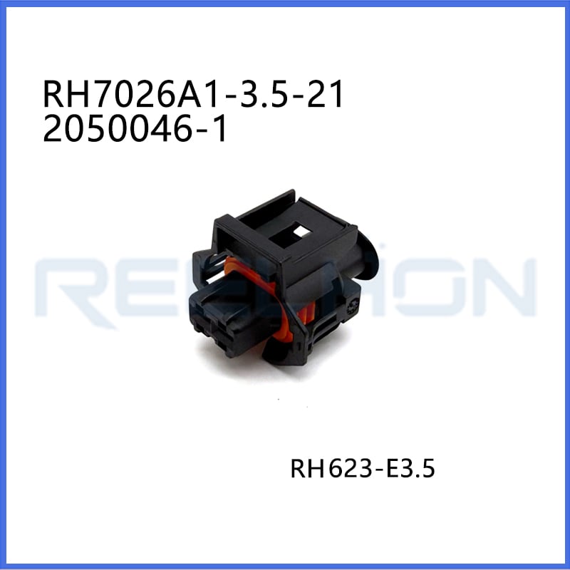
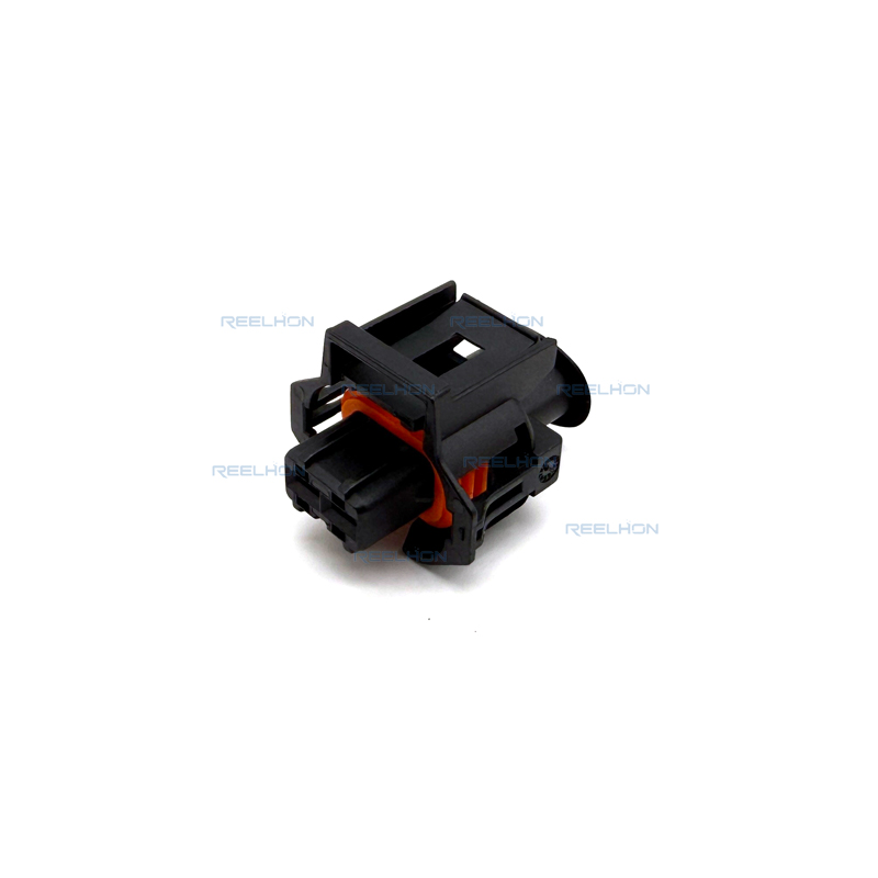
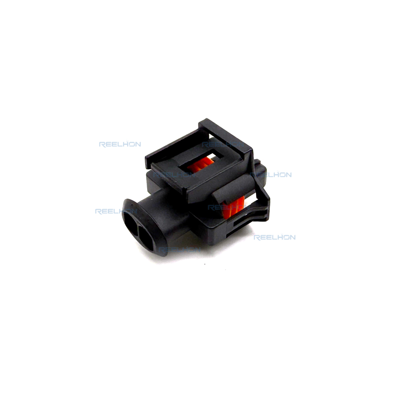
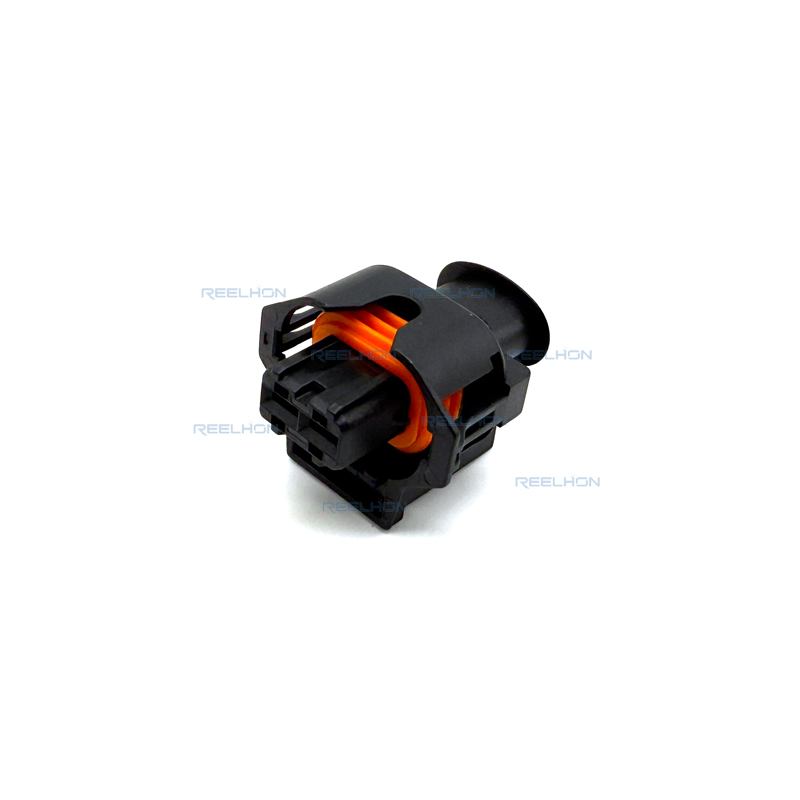
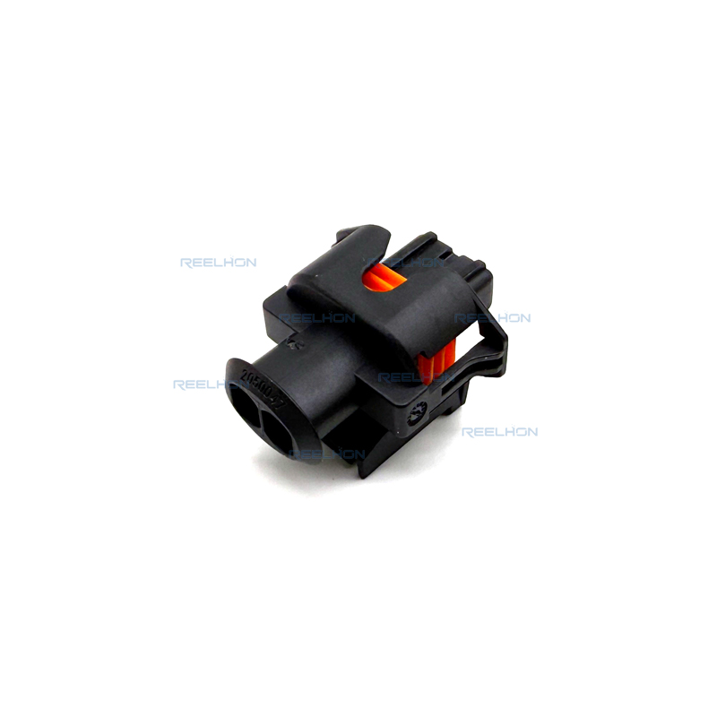
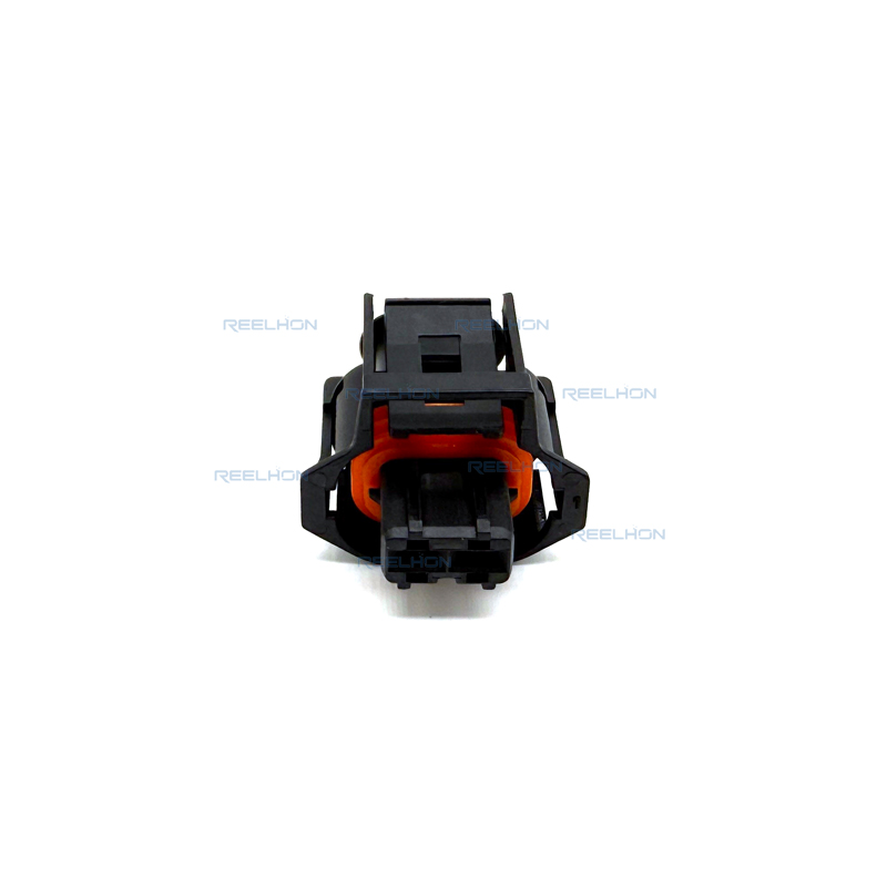
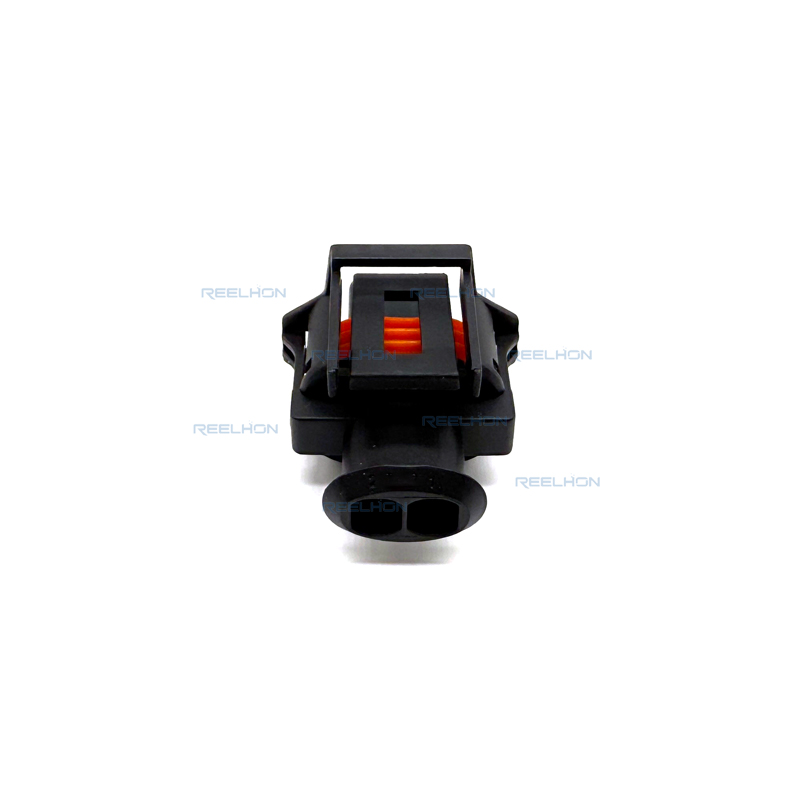
TE Internal Part Number: 2050046-1
TE Internal Description: 2POS 2.8MM SENSOR PLUG ASSY.
Connector & Housing Type: Plug
Number of Positions: 2
Number of Rows: 1
Terminal Type:Receptacle (Female)
Mating Tab Width:2.8 mm [.11 in]
Centerline (Pitch): 5 mm [.197 in]
Mounting Type: Cable Mount (Free-Hanging)
Sealable: Yes
Primary Product Color: Black
Nominal Voltage Architecture (V): 12, 24, 48
Operating Voltage (VDC) :50
Connector Height:30.5 mm [1.201 in]
Product Length:25 mm [.984 in]
Product Width:20.1 mm [.791 in]
Housing Material:PA 66 GF15
UL Flammability Rating: UL 94HB
Packaging Method: Box
Packaging Quantity :600
The TE Connectivity (formerly AMP) 2050046-1 is a 2-position, 1-row, sealed plug assembly from the 2.8 mm Sensor Flat Type Receptacle System. This connector is designed for automotive and industrial applications requiring reliable signal transmission in environments where moisture or dust may be present. The plug is sealable and intended for cable mount (free-hanging) installation, making it suitable for inline connections or as a counterpart to a header or device connector. The housing is molded in black PA 66 GF15 (glass-fiber reinforced polyamide), providing mechanical strength and dimensional stability.
This connector uses 2.8 mm receptacle (female) terminals that mate with 2.8 mm male tabs (pin diameter 2.8 mm / 0.11 in). The contact system is based on the proven AMP Sensor Flat type design, which ensures low contact resistance and high vibration resistance. The nominal voltage architecture supports 12 V, 24 V, and 48 V systems, with a maximum working voltage of 50 VDC. The 5 mm centerline (pitch) provides adequate spacing for medium-current signal applications.
Structural and Mechanical Characteristics
The 2050046-1 plug features a rectangular shape with an integral housing locking interface. It has a primary locking feature that is housing-integrated, ensuring secure mating with the corresponding header or device connector. The connector orientation is straight (180° wire exit angle). Mating alignment is provided via a keying system (connector key code 1), preventing incorrect mating. Terminal position assurance (TPA) is not provided as a standard feature, but stress relief can be added as an accessory according to the product specification.
The dimensions of the connector are as follows: height 30.5 mm (1.201 in), length 25 mm (0.984 in), width 20.1 mm (0.791 in). The housing material is PA 66 GF15 (polyamide 66 with 15% glass fiber reinforcement), which offers good resistance to heat, chemicals, and mechanical stress. The UL flammability rating is UL 94HB.
The connector is sealable (Sealable = Yes). This indicates that when mated with a corresponding sealed header and equipped with appropriate wire seals (single wire seals) and cavity plugs for unused cavities, the interface can achieve protection against water ingress. The system is designed for harsh underhood and sensor applications. Unused cavities can be sealed using dead end plugs as described in the application specification (refer to section 6.3 of specification 114-18144-1). The dead end plugs are positioned in the cavity to maintain sealing integrity.
The 2050046-1 plug is designed to accept 2.8 mm receptacle contacts. The application of these contacts must follow the guidelines in AMP specification 114-18144-1. The following requirements are extracted from that specification and apply to the contacts used with this plug assembly.
Wire Types: Only conductors in accordance with DIN 72 551 (FLR – thin-wall low-tension cables) may be used. Other conductors require approval from the development department. The wires are processed as single terminations.
Wire Preparation: The wire must be stripped to the lengths specified in Table 1 (for contacts with insulation crimp) or Table 2 (for contacts with single wire seal). Individual strands must not be bent, damaged, or cut. When using single wire seals, the insulation in the sealing area must not be damaged, compressed, or deformed. The insulation surface must be clean and free of contamination.
Cut-off and Burr: After crimping, the cut-off must be visible, with a maximum length of 0.3 mm. The burr at the shearing point may not exceed 0.03 mm.
Wire Crimp Position: The wire end must extend 0.1 to 0.7 mm beyond the front edge of the wire crimp. The insulation end must never be crimped inside the wire crimp.
Crimp Height Measurement: The crimp height shall be measured as described in instruction sheet IS 7424 using a crimp height micrometer (AMP Order No. 675836-0). The crimp width is tool-dependent and defined as the distance between the tangent points of the two rolling radii. Production monitoring by measuring crimp width is not possible.
Extraction Forces: The extraction forces of the crimped contacts must fulfill the requirements of DIN IEC 352 part 2.
Crimp Bellmouth: The rear bellmouth size depends on the wire range: for 0.5 – 2.5 mm², the bellmouth is 0.40 ± 0.20 mm. A missing front bellmouth is permitted.
Burr on Crimp Base: The burr on the base of the crimp may not exceed 0.15 mm (width and height), which is a deviation from the general specification 114-18022.
Insulation Crimp (for wires without seal): The end of the insulation must be visible in the transition between wire crimp and insulation crimp. The insulation must at least reach the front edge of the insulation crimp, but must never be crimped in the wire crimp. The crimp height is adjusted according to bending test DIN 41611 part 3 or wrapping test DIN EN 60352 part 2.
Single Wire Seal Crimp (if used): The end of the wire insulation must be at least flush with the front face of the seal and may extend not more than 1.0 mm beyond it. The crimp height is correctly adjusted when the crimp encloses the seal in a circular shape. The collar of the single wire seal must be visible in the window of the crimp base. After crimping, the seal must have no visible cuts or notches around the collar diameter; only pressure points that will not cause long-term tearing or splitting are permitted.
Contact Area: After crimping, the cantilever spring, locking lance, and contact body must not be bent or deformed.
Shape and Position Tolerances: The bottom of the wire crimp and insulation crimp must be parallel to the contact body within 0.3 mm. The insulation crimp width must be symmetrical to the contact body within 0.3 mm. For single wire seal versions, the lateral offset of the seal crimp must be within 0.3 mm symmetrical to the contact body, and the seal itself must lie within a vertical symmetry tolerance of 1 mm.
Extraction Tool: For removing contacts from the housing, use extraction tool Order No. 968 928-1.
Assembly Tool: For inserting contacts with single wire seals into the housing, assembly tool Order No. 519609-1 may be used. The tool is positioned on the wire with an air gap of approximately 1.5 mm between its front edge and the seal end. By slightly opening the tool, the seal can be pushed into position.
Based on the TE Connectivity declaration provided for part number 2050046-1: EU RoHS (2011/65/EU) – Compliant, including Delegated Directive 2015/863/EU.
EU ELV Directive 2000/53/EC: Compliant.
China RoHS 2 (MIIT Order No. 32, 2016): No restricted substance(s) above threshold.
EU REACH Regulation (EC) No. 1907/2006: Does not contain REACH SVHC. ECHA Candidate List: February 2026 (253 substances declared). SVHC declaration updated to February 2026.
Halogen Content: Not low halogen – contains Br or Cl > 900 ppm (but BFR/CFR/PVC-free).
Solder Process Capability: Not suitable for soldering processes (the connector is designed for crimp termination, not soldering).
Repairability: The connector is serviceable (Repairable = Yes).
The TE 2050046-1 is a robust, sealable 2-position plug for 2.8 mm sensor and signal applications in 12/24/48 V electrical systems. It features a glass-reinforced PA66 housing, 5 mm pitch, free-hanging mounting, and compatibility with AMP’s 2.8 mm receptacle contacts. When crimped according to specification 114-18144-1 (using approved AMP crimp tools and following wire preparation, crimp height, and bellmouth guidelines), the connector system provides reliable, vibration-resistant connections. The product is fully compliant with RoHS, ELV, and REACH (SVHC-free) regulations, making it suitable for global automotive and industrial markets.
| Connector & Housing Type | Plug |
| Connector Shape | Rectangular |
| Hybrid Connector | No |
| Sealable | Yes |
| Primary Locking Feature | Housing Integrated |
| Connector and Terminal End To | Wire & Cable |
| Structural Characteristics | |
| Number of Positions | 2 |
| Number of Rows | 1 |
| Electrical Characteristics | |
| Operating Voltage (VDC) | 50 V |
| Nominal Voltage Architecture | 12 V, 24 V, 48 V |
| Body Characteristics | |
| Wire Exit Angle | 180° |
| Primary Product Color | Black |
| Connector Key Code | 1 |
| Contact Characteristics | |
| Terminal Type | Receptacle (Female) |
| Terminal Size | 2.8 mm |
| Mating Tab Width | 2.8 mm [.11 in] |
| Mechanical Attachment | |
| Mating Alignment | Provided |
| Mating Alignment Type | Keyed |
| Terminal Position Assurance | No |
| Stress Relief | Added by accessory |
| Connector Mounting Type | Cable Mount (Free-Hanging) |
| Housing Characteristics | |
| Housing Material | PA 66 GF15 |
| Centerline (Pitch) | 5 mm [.197 in] |
| Dimensions | |
| Connector Height | 30.5 mm [1.201 in] |
| Product Length | 25 mm [.984 in] |
| Product Width | 20.1 mm [.791 in] |
| Industry Standards | |
| UL Flammability Rating | UL 94HB |
| Packaging Characteristics | |
| Packaging Method | Box |
| Packaging Quantity | 600 |
| Other | |
| Serviceable | Yes |
| Connector Position Assurance | No |
| Compliance | |
| EU RoHS (2011/65/EU) | Compliant |
| EU ELV Directive 2000/53/EC | Compliant |
| China RoHS 2 | No Restricted Substance(s) Above Threshold |
| EU REACH (EC) No. 1907/2006 | Does not contain REACH SVHC |
| Halogen Content | Not low halogen (Br or Cl > 900 ppm) – BFR/CFR/PVC-free |
| Solder Process Capability | Not suitable for soldering processes |

Be the first to get our latest styles and offers.
5th Floor, Building 23, Phase 3, Tingtian Micro Park, Ruian City, Wenzhou, Zhejiang Province
Copyright © 2026 Ruian Ruihong Trading Co., Ltd. All rights reserved. - Privacy Policy
 EN
EN