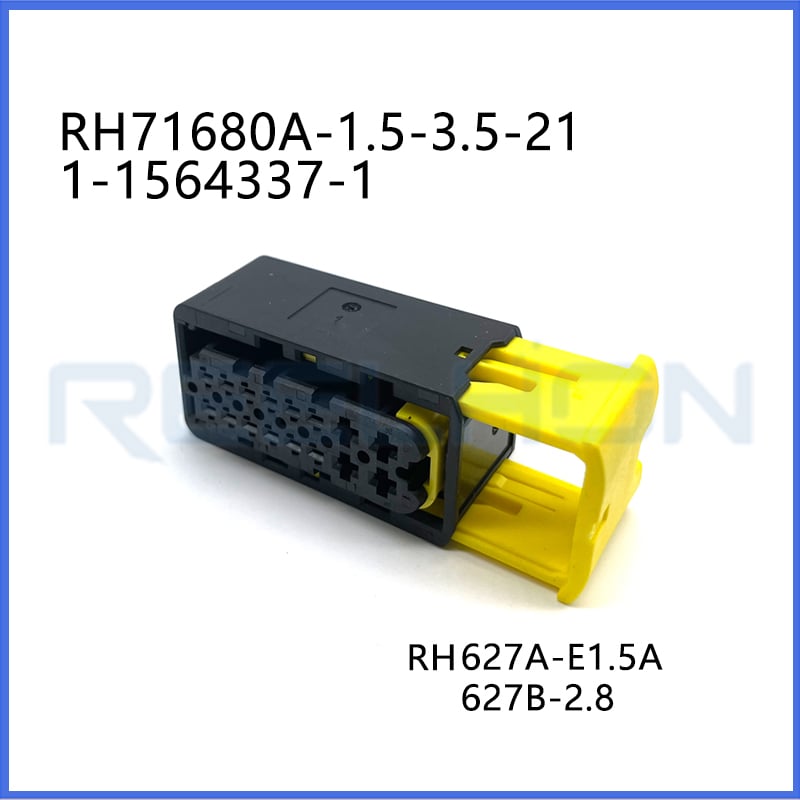
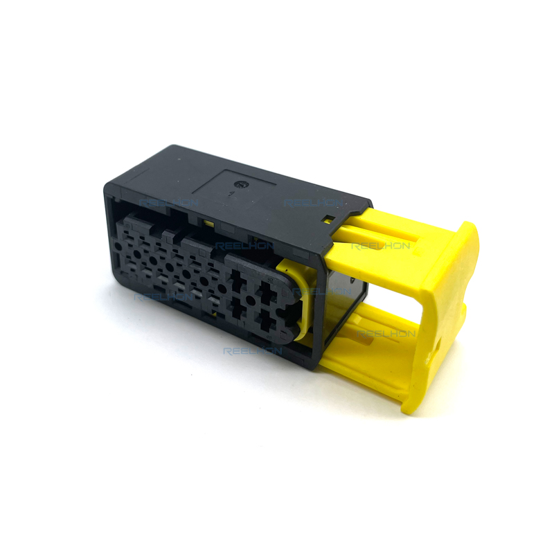
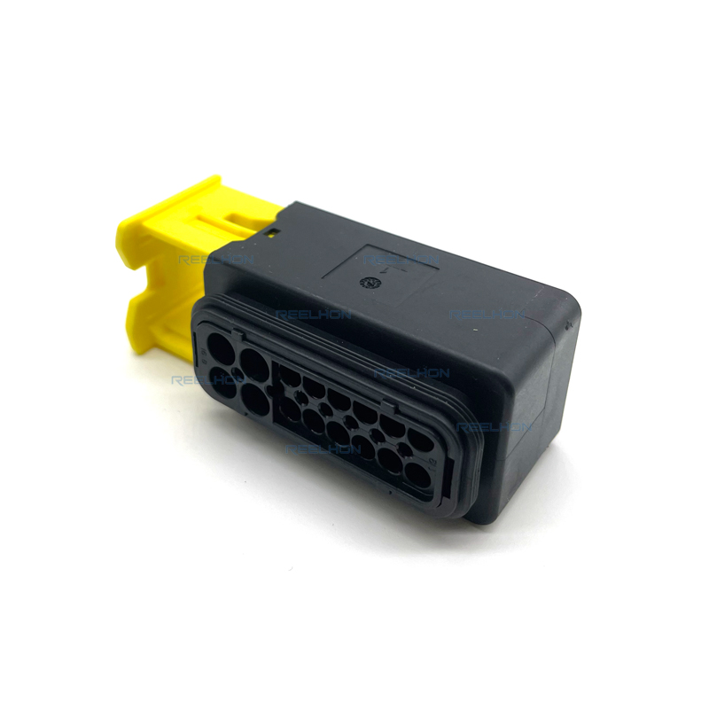
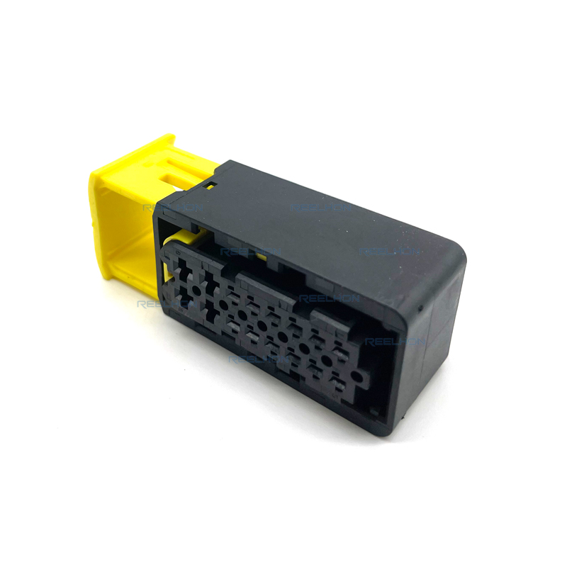
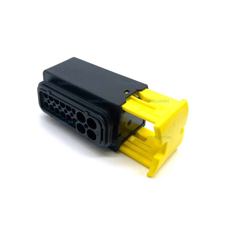
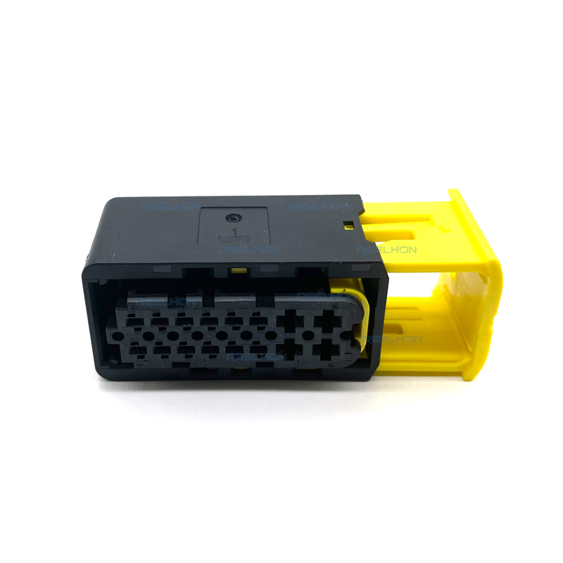
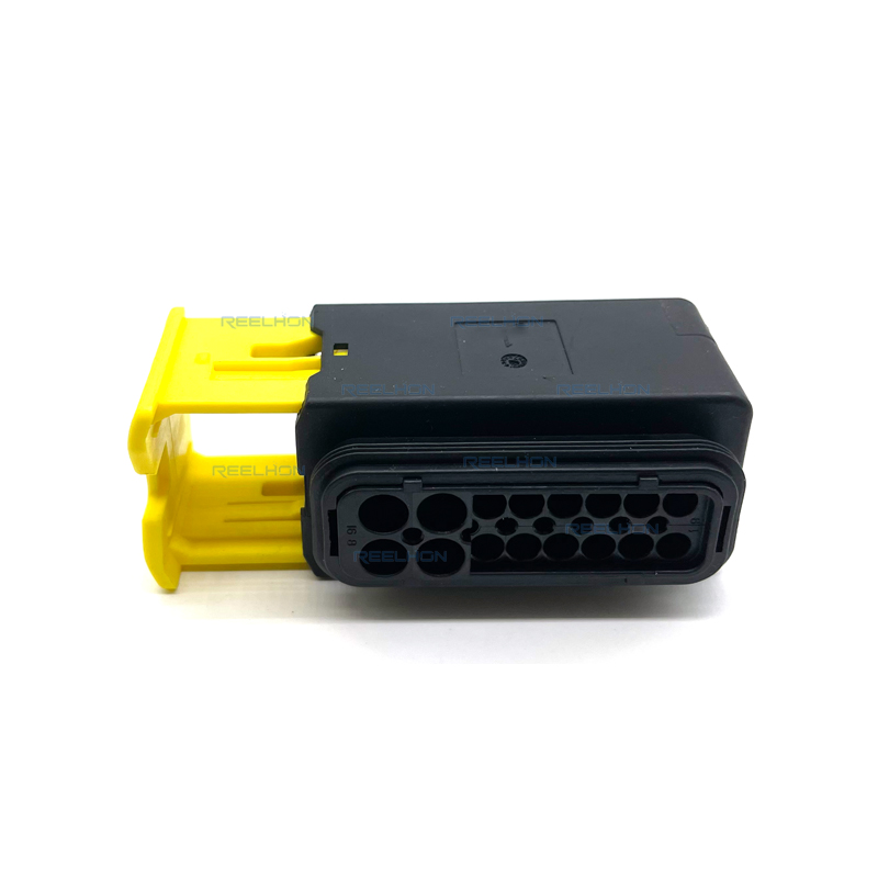
TE Internal Part Number: 1-1564337-1
TE Internal Description: 16POS, MIXED, REC HSG, ASSY
Connector & Housing Type: Receptacle Housing (Female)
Number of Positions: 16
Number of Rows: 2
Hybrid Connector: Yes
Sealable: Yes
Primary Product Color: Black
Connector & Key Code: A
Terminal Types: 1.5K and 2.8 mm
Mating Tab Width: 1.5 mm [.059 in] and 2.8 mm [.11 in]
Maximum Current Rating: 40 A
Centerline (Pitch): 4 mm and 6 mm [.157 in and .236 in]
Mounting Type: Cable Mount (Free-Hanging)
Housing Material: PBT GF30
Operating Temperature Range: -40°C to 140°C [-40°F to 284°F]
IP Rating: IP67
UL Flammability Rating: UL 94V-0
Packaging Quantity: 230
The TE Connectivity 1-1564337-1 is a 16-position, 2-row, sealed receptacle housing from the Heavy Duty Sealed Connector Series (HDSCS). This connector family is designed for wire-to-wire applications and accepts AMP MCP contact systems with single-wire sealing (SWS). The housing is a mixed version, supporting both AMP MCP 1.5K and AMP MCP 2.8 contact systems within the same connector, allowing flexibility in current carrying capacity. The nominal voltage architecture supports 12 V, 24 V, and 48 V systems, with a maximum working voltage of 60 VDC. The connector is fully sealable and rated IP67, providing protection against water and dust ingress for demanding automotive and industrial environments.
The housing is molded in black PBT GF30 (glass-fiber reinforced polyethylene terephthalate), offering high mechanical strength and thermal stability. The operating temperature range is from -40°C to 140°C. The connector features two different centerline pitches: 4 mm for the smaller contacts and 6 mm for the larger contacts. The product dimensions are as follows: height 31.25 mm, length 67.2 mm, width 25.7 mm.
The Heavy Duty Sealed Connector Series is available in 2 to 18 positions, and this 16-position receptacle housing is designed to mate with a corresponding tab housing (not specified in the provided material). The connector is equipped with a secondary locking device that is delivered in the pre-locked position. Contacts can only be inserted when the secondary locking device is in the pre-locked position. After all contacts are loaded, the secondary locking device must be moved into the final locked position, which provides an additional retaining force for the terminals if the primary lock fails. Reaching the correctly locked position is signaled by an audible click.
Coding and polarization features prevent mis-mating. The connector uses key code A. The housing latch will lock and provide an audible and tactile click when the plug and receptacle have reached the fully mated position. For connectors that require unmating, a slide (present on the receptacle housing) must be returned to the pre-locked position. The use of a simple aid or tool (e.g., a screwdriver or a small wrench up to size 8) can assist this operation. A mechanical stop and a soft click indicate that the pre-locked position is reached.
This mixed receptacle housing accepts two types of AMP MCP contacts with single-wire sealing:
AMP MCP 1.5K contacts (for smaller gauge wires)
AMP MCP 2.8 contacts (for larger gauge wires)
The maximum permitted wire size depends on the contact system. For detailed information on each contact system, refer to the respective customer drawings and application specifications: AMP MCP 1.5K (application spec 114-18386) and AMP MCP 2.8 (application spec 114-18148-1). The terminal current rating maximum is 40 A, which is achieved with the larger 2.8 mm contacts.
The receptacle housing is designed for wires terminated with contacts that include individual wire seals (single-wire sealing system). The appropriate size wire seal must be selected to accommodate the insulation diameter of the wire being used. The wire seal must be placed on the end of the wire prior to termination. The wire must be stripped to the dimensions specified in the contact application specifications. Do not nick, scrape, or cut the wire conductor during stripping. Do not damage the wire seal when placing it over the wire.
Contacts can only be inserted when the secondary locking device is in the pre-locked position. Correct orientation of the contacts must be ensured. If the orientation is incorrect, the contacts cannot be fully inserted, causing the crimp area to protrude from the housing. When orientation is correct, the locking of the contacts in the cavity will be confirmed by an audible click. Additionally, the contact crimps and single wire seals are located completely in the cavity. After all contacts have been inserted, the secondary locking device must be moved into the final locked position. Reaching the correctly locked position is signaled by an audible click. Note that the secondary locking device does not stringently detect the correct position of the terminal in the cavity; correct contact location must be assured before the secondary locking device is activated.
Unused cavities must be closed with cavity plugs to maintain the water-tight integrity of the connector system. Cavity plug part numbers are shown on the contact drawings or in the contact specification. The cavity plug can be assembled manually or with an auxiliary tool. The defined insertion depth of 1 to 3 mm must be met. During assembly, care must be taken to avoid damaging the sealing lips. The insertion direction is from the wiring side of the housing.
The secondary locking device must be in the pre-locked position before extracting contacts. The blades of an extracting tool (refer to the contact application specification for tool details) must be inserted from the mating side into the two slots of the contact cavity until they stop, which unlocks the contact. The tool remains in position, and the contact can then be extracted by pulling on the cable. Do not pull the cable before unlocking the contact. By pushing the cable gently against the cable release direction, the unlocking procedure becomes easier.
The connectors described in this specification are equipped with three protection features: coding and polarization, position control of the secondary locking device, and position control of the receptacle housing to the counterpart. If the secondary locking device is not in the locked position, the connectors cannot be mated with normal force. Mating should only be done when the secondary locking device is completely locked. The receptacle connector has a slide as a mating and unmating assist, which is in the pre-locked position as delivered. Without the counterpart, the slide cannot be actuated with normal force. Only after the connector is offered up to the counterpart until it stops is the slide unlocked. Then the slide can be actuated and mating completed. To unmate, the slide must be returned to the pre-locked position. Connector mating and unmating under load is not permitted.
Tab housings (the mating counterpart) without flange can be fixed with a cable tie or a Raymond clip, but fixation with a clip is only possible in certain housing groups. For tab housings with flange, mounting is achieved with a fixing slide. The preferred mounting direction of the fixing slide is shown in the application specification. If a sealing function is required, the flange with the axial seal must be on the dry side (protection against high pressure water jet). For ice-water shock performance according to ISO 16750-4, supporting of the axial seal is recommended.
Covers are available with 90° and 180° cable exits to protect wires, single-wire seals, and cavity plugs from environmental influences and cleaning processes. The cover is mounted by offering the cover shell with locking hooks to the housing and snapping it closed. A mechanical stop and a soft click indicate that the cover is in place. Dismounting of 90° and 180° covers is aided by using a screwdriver to release the locking latches. Protection caps are also available for socket housings, tab housings, and tab headers to provide water and dust proofing to IP67/IP69k.
Based on the TE Connectivity declaration provided for part number 1-1564337-1: EU RoHS (2011/65/EU) – Compliant, including Delegated Directive 2015/863/EU. EU ELV Directive 2000/53/EC – Compliant. China RoHS 2 – No restricted substance(s) above threshold. EU REACH Regulation (EC) No. 1907/2006 – Does not contain REACH SVHC. ECHA Candidate List: February 2026 (253 substances declared). Halogen Content: Not low halogen – contains Br or Cl > 900 ppm. Solder Process Capability: Not suitable for soldering processes.
The TE Connectivity 1-1564337-1 is a 16-position, 2-row, mixed, sealed receptacle housing designed for heavy-duty wire-to-wire applications. It supports AMP MCP 1.5K and 2.8 contact systems, is rated IP67, and operates from -40°C to 140°C. The housing features black PBT GF30 material, key code A, and two pitch sizes (4 mm and 6 mm). When used with correct contacts, wire seals, cavity plugs, and proper secondary locking activation, the connector provides reliable, sealed power and signal transmission for automotive and industrial applications, meeting RoHS, ELV, and REACH SVHC-free compliance.
| Product Type Features | |
| Connector & Housing Type | Receptacle Housing |
| Connector Shape | Rectangular |
| Hybrid Connector | Yes |
| Sealable | Yes |
| Primary Locking Feature | On Terminal |
| Connector System | Wire-to-Wire |
| Connector and Terminal End To | Wire & Cable |
| Structural Characteristics | |
| Number of Positions | 16 |
| Number of Rows | 2 |
| Electrical Characteristics | |
| Operating Voltage (VDC) | 60 V |
| Nominal Voltage Architecture | 12 V, 24 V, 48 V |
| Maximum Current Rating | 40 A |
| Circuit Application | Power |
| Body Characteristics | |
| Wire Exit Angle | 90°, 180° |
| Primary Product Color | Black |
| Connector & Key Code | A |
| Housing Material | PBT GF30 |
| Centerline (Pitch) | 4 mm and 6 mm [.157 in and .236 in] |
| Contact Characteristics | |
| Terminal Type | Receptacle (Female) |
| Terminal Size | 1.5K, 2.8 mm |
| Mating Tab Width | 1.5 mm [.059 in], 2.8 mm [.11 in] |
| Mechanical Attachment | |
| Mating Alignment | Provided |
| Mating Alignment Type | Keyed |
| Terminal Position Assurance | No |
| Stress Relief | Not provided |
| Connector Mounting Type | Cable Mount (Free-Hanging) |
| Dimensions | |
| Connector Height | 31.25 mm [1.23 in] |
| Product Length | 67.2 mm [2.646 in] |
| Product Width | 25.7 mm [1.012 in] |
| Environmental Characteristics | |
| Operating Temperature Range | -40°C to 140°C [-40°F to 284°F] |
| Maximum Operating Temperature | 140°C [284°F] |
| Industry Standards | |
| IP Rating | IP67 |
| UL Flammability Rating | UL 94V-0 |
| Packaging Characteristics | |
| Packaging Method | Box (bulk) |
| Packaging Quantity | 230 |
| Other | |
| Serviceable | Yes |
| Connector Position Assurance | No |
| Compliance | |
| EU RoHS (2011/65/EU) | Compliant |
| EU ELV Directive 2000/53/EC | Compliant |
| China RoHS 2 | No Restricted Substance(s) Above Threshold |
| EU REACH (EC) No. 1907/2006 | Does not contain REACH SVHC |
| Halogen Content | Not low halogen (Br or Cl > 900 ppm) |
| Solder Process Capability | Not suitable for soldering processes |

Be the first to get our latest styles and offers.
5th Floor, Building 23, Phase 3, Tingtian Micro Park, Ruian City, Wenzhou, Zhejiang Province
Copyright © 2026 Ruian Ruihong Trading Co., Ltd. All rights reserved. - Privacy Policy
 EN
EN