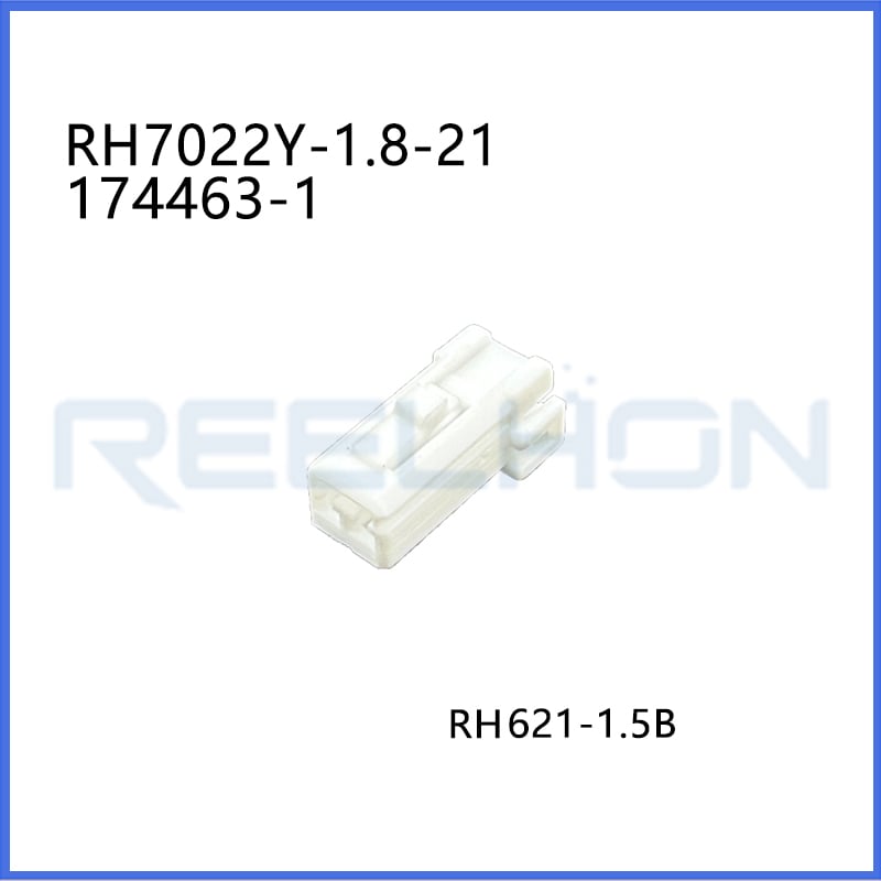
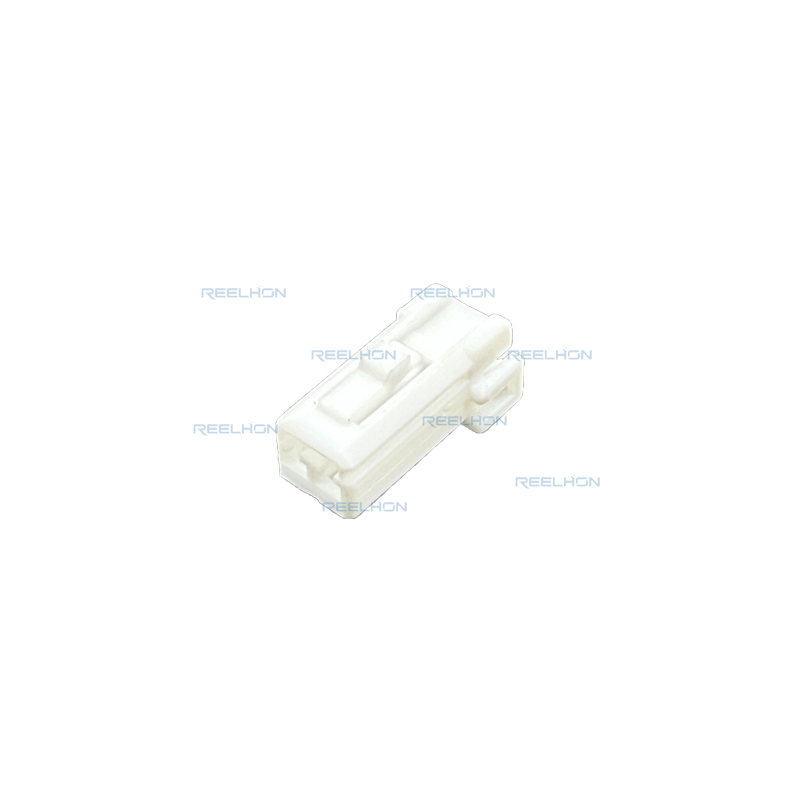
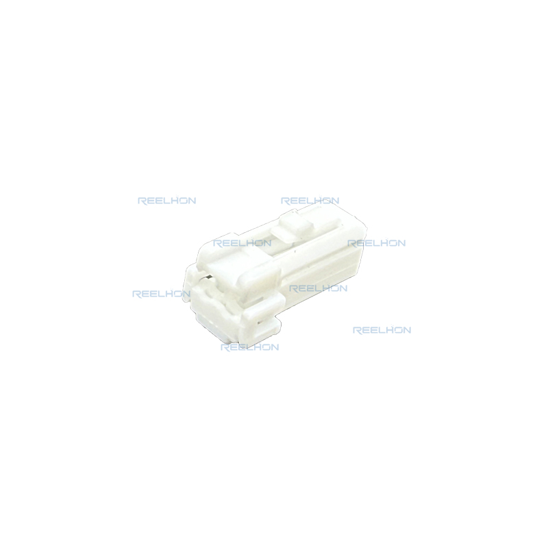
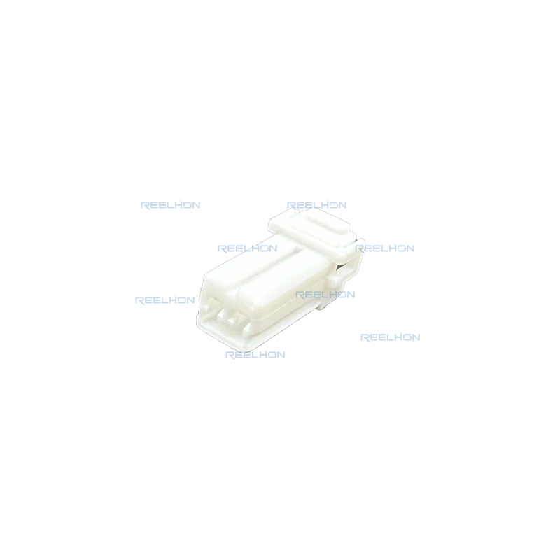
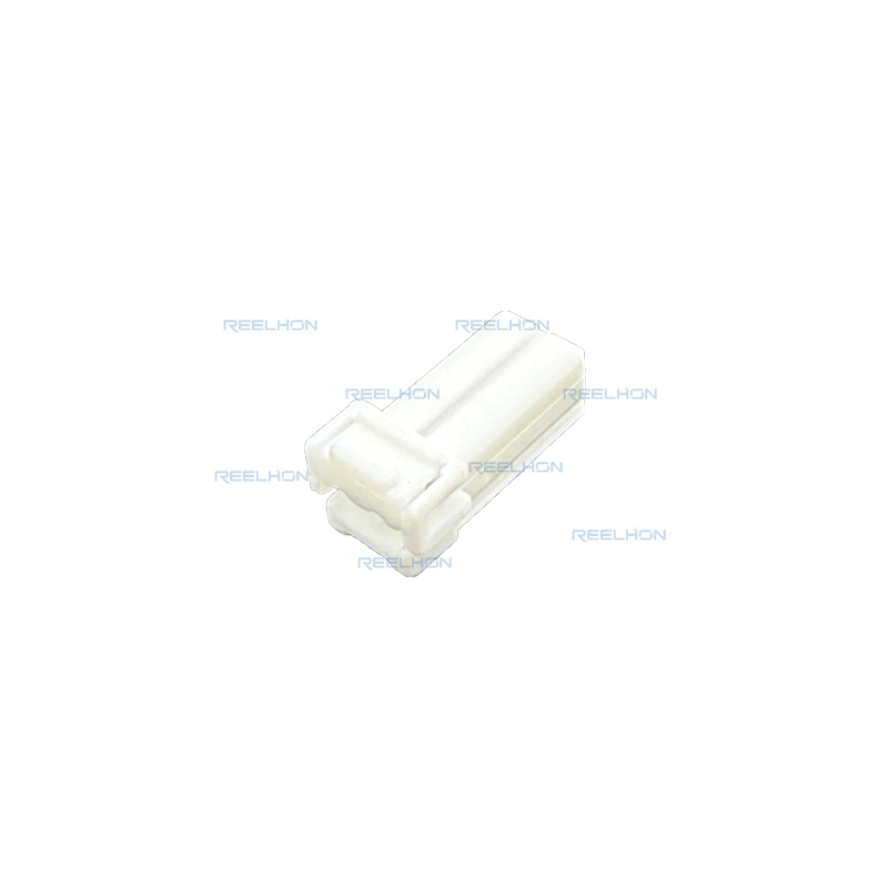
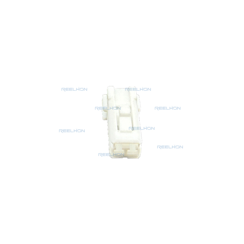
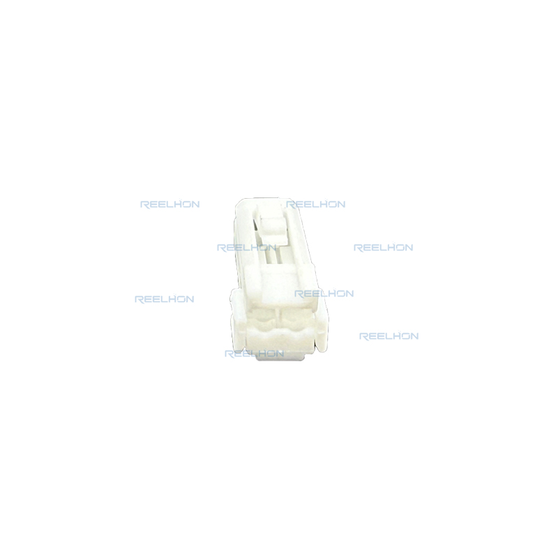
TE Internal Part Number: 174463-1
TE Internal Description:070 MULTILOCK 2P P
Connector & Housing Type:Receptacle Housing (Female Terminal Housing)
Number of Positions:2
Number of Rows:1
Sealable:No
Primary Product Color: Natural (Light Brown)
Terminal Type: Receptacle (Female)
Terminal Size:1.8 mm
Mating Tab Width:1.8 mm [.07 in]
Centerline (Pitch): 3.5 mm [.13 in]
Mounting Type: Cable Mount (Free-Hanging)
Housing Material: Polybutylene Terephthalate (PBT)
Operating Temperature Range: -30°C to 105°C [-22°F to 221°F]
Nominal Voltage Architecture: 12 V
Wire Size Range (based on contact options): 0.2 mm² to 1.25 mm² (see contact part numbers)
UL Flammability Rating: UL 94HB
Packaging Method:Tray
Packaging Quantity: 4000
The TE Connectivity 174463-1 is a 2-position, 1-row, unsealed receptacle housing from the 070 Series MULTILOCK I/O Connector (MLC) system. This connector is designed for wire-to-wire applications and accepts 070 series receptacle contacts. The housing is molded in natural (light brown) Polybutylene Terephthalate (PBT) resin. The nominal voltage architecture is 12 V, with a working voltage of 12 VDC. The operating temperature range is from -30°C to 105°C. The centerline pitch is 3.5 mm, and the connector dimensions are: height 15.15 mm, length 10.4 mm, width 21 mm. This connector is non-sealable and is intended for applications where environmental sealing is not required.
The 070 MULTILOCK I/O connector family includes plug housings (cap housings) and receptacle housings (plug housings) in various positions from 2 to 20 ways. The 174463-1 is the 2-position receptacle housing, which mates with a corresponding 2-position cap housing (e.g., 174460). The connector system is widely used in automotive and industrial signal and low-power applications.
The receptacle housing accepts 070 series receptacle contacts in two sizes: S type for smaller wires and M type for larger wires. Based on the product specification 108-5264, the applicable receptacle contacts are:
173630: Receptacle Contact (0.2 – 0.3 mm²) S Type
173631: Receptacle Contact (0.5 – 1.25 mm²) M Type
The corresponding tab contacts (for the mating housing) are:
173633: Tab Contact (0.2 – 0.3 mm²) S Type
173645: Tab Contact (0.5 – 1.25 mm²) M Type
The maximum current carrying capacity per contact is determined by wire size and number of positions. For a single contact (not de-rated), the maximum current is: 0.2 mm² – 6 A, 0.3 mm² – 8 A, 0.5 mm² – 11 A, 0.85 mm² – 15 A, 1.25 mm² – 19 A. For a 2-position connector, a reduction coefficient of 0.75 applies (according to Figure 7 of the specification). Therefore, the acceptable current for a 2-position assembly is the specified maximum current multiplied by 0.75.
The 070 MULTILOCK connector is designed to meet the electrical, mechanical, and environmental performance requirements specified in Figure 2 of the specification. Key requirements include:
Termination Resistance (Low Level): Shall meet specified initial and final values (100 mΩ Max. after environmental tests).
Dielectric Strength: No breakdown or flashover.
Insulation Resistance: 100 MΩ minimum at 500 VDC, measured between adjacent circuits of mated connectors.
Current Leakage: 3 mA maximum under 12 VDC, 60°C, 90-95% humidity for 1 hour.
Temperature Rise: Under specified current, temperature rise shall be 60°C maximum.
Contact Mating Force: 2.9 – 7.8 N per contact (operation speed 100 mm/min).
Contact Unmating Force: 2 – 7.8 N per contact (operation speed 100 mm/min).
Connector Locking Strength: Measured per AMP Spec 109-5210.
Contact Insertion Force: Measured per AMP Spec 109-5211.
Contact Retention Force (Primary Lock): 59 N minimum. Apply axial pull-off load to crimped wire at 100 mm/min.
Contact Retention Force (Secondary Lock): 78.5 N minimum (when secondary lock is engaged – note that this housing may or may not have a secondary lock; the product drawing should be consulted).
Crimp Tensile Strength (minimum values):
0.2 mm² (#24 AWG): 68.6 N
0.3 mm² (#22 AWG): 78.5 N
0.5 mm² (#20 AWG): 88 N
0.85 mm² (#18 AWG): 127 N
1.25 mm² (#16 AWG): 177 N
Current Cycling: 200 cycles (45 min ON, 15 min OFF). Final termination resistance 10 mΩ max, no ignition allowed.
Vibration (High Frequency): Frequency 20-200 cycles/minute, acceleration 44 m/s², 8 hours each in X, Y, Z directions. No discontinuity >1 μsec.
Physical Shock: No discontinuity >1 μsec.
Durability (Repeated Mating/Unmating): 30 cycles, final termination resistance 10 mΩ max.
Resistance to “Kojiri” (oblique mating): 30 cycles by hand, final termination resistance 10 mΩ max.
Thermal Shock: -50°C for 120 minutes, then 120°C for 120 minutes, 5 cycles. Final termination resistance 10 mΩ max.
Humidity (Steady State): Mated connectors, 90-95% RH at 60°C for 48 hours. Final termination resistance 10 mΩ max, current leakage 3 mA max.
Salt Spray: Unmated connectors exposed to 5% salt concentration for 48 hours (MIL-STD-202, Method 101). Final termination resistance 10 mΩ max.
Industrial Gas (SO₂): 10 ppm SO₂, 95% RH at room temperature for 24 hours. Final termination resistance 10 mΩ max.
Temperature Life (Heat Aging): 120°C for 120 hours. Final termination resistance 10 mΩ max.
Resistance to Cold: -50°C ±5°C for 120 hours. Final termination resistance 10 mΩ max.
Icing: Immerse in boiling water for 60 minutes, freeze at -30°C. Final termination resistance 10 mΩ max.
Dust Bombardment: Subject to JIS R5210 cement blow (1.5 kg per 10 seconds in 15-minute intervals for 60 minutes). Final termination resistance 10 mΩ max.
Contacts must be crimped in accordance with Application Specification 114-5091, 114-5092 (Termination of 070 Series Receptacle Contacts). The test samples used for performance tests must be prepared according to these specifications. The crimp tensile strength values listed above must be achieved.
The 174463-1 receptacle housing has a rectangular shape with a primary locking feature on the terminal. The connector system is wire-to-wire. Mating alignment is provided via polarization (keying). The wire exit angle is 180° (straight). Terminal position assurance (TPA) is not provided, and stress relief is not included. The connector is not serviceable (Repairable = No). The UL flammability rating is UL 94HB.
The 174463-1 receptacle housing mates with a corresponding 2-position cap housing (plug housing) of the 070 MULTILOCK series. The recommended mating cap housing part numbers include 174460 (2-position cap housing) or similar. When mating, ensure proper polarization alignment. The housing latch will provide tactile feedback. For unmating, press the latch and pull apart.
Based on the TE Connectivity declaration provided for part number 174463-1: EU RoHS (2011/65/EU) – Compliant, including Delegated Directive 2015/863/EU. EU ELV Directive 2000/53/EC – Compliant. China RoHS 2 – No restricted substance(s) above threshold. EU REACH Regulation (EC) No. 1907/2006 – Does not contain REACH SVHC. ECHA Candidate List: February 2026 (253 substances declared). Halogen Content: Low halogen – Br, Cl, F < 900 ppm per homogeneous material, and also BFR/CFR/PVC-free. Solder Process Capability: Not suitable for soldering processes.
The TE 174463-1 is a 2-position, 1-row, unsealed receptacle housing for the 070 MULTILOCK I/O connector system. It accepts 1.8 mm receptacle terminals (S type for 0.2-0.3 mm² wires, M type for 0.5-1.25 mm² wires), operates at 12 V, and has a temperature range of -30°C to 105°C. The housing is made of PBT, natural color, with a 3.5 mm pitch. It is designed for free-hanging cable mounting and provides reliable electrical and mechanical performance meeting the requirements of product specification 108-5264, including vibration, thermal shock, humidity, salt spray, and durability tests. The product is RoHS, ELV, and REACH SVHC compliant, with low halogen content.
| Product Type Features | |
| Connector & Housing Type | Receptacle Housing |
| Connector Shape | Rectangular |
| Hybrid Connector | No |
| Sealable | No |
| Primary Locking Feature | On Terminal |
| Connector System | Wire-to-Wire |
| Connector and Terminal End To | Wire & Cable |
| Structural Characteristics | |
| Number of Positions | 2 |
| Number of Rows | 1 |
| Electrical Characteristics | |
| Operating Voltage (VDC) | 12 V |
| Nominal Voltage Architecture | 12 V |
| Circuit Application | Power |
| Body Characteristics | |
| Wire Exit Angle | 180° |
| Primary Product Color | Natural (Light Brown) |
| Housing Material | Polybutylene Terephthalate (PBT) |
| Centerline (Pitch) | 3.5 mm [.13 in] |
| Contact Characteristics | |
| Terminal Type | Receptacle (Female) |
| Terminal Size | 1.8 mm |
| Mating Tab Width | 1.8 mm [.07 in] |
| Mechanical Attachment | |
| Mating Alignment | Provided |
| Mating Alignment Type | Polarized |
| Terminal Position Assurance | No |
| Stress Relief | Not provided |
| Connector Mounting Type | Cable Mount (Free-Hanging) |
| Dimensions | |
| Connector Height | 15.15 mm [.59 in] |
| Product Length | 10.4 mm [.409 in] |
| Product Width | 21 mm [.828 in] |
| Environmental Characteristics | |
| Operating Temperature Range | -30°C to 105°C [-22°F to 221°F] |
| Maximum Operating Temperature | 105°C [221°F] |
| Industry Standards | |
| UL Flammability Rating | UL 94HB |
| Packaging Characteristics | |
| Packaging Method | Tray |
| Packaging Quantity | 4000 |
| Other | |
| Serviceable | No |
| Connector Position Assurance | No |
| Compliance | |
| EU RoHS (2011/65/EU) | Compliant |
| EU ELV Directive 2000/53/EC | Compliant |
| China RoHS 2 | No Restricted Substance(s) Above Threshold |
| EU REACH (EC) No. 1907/2006 | Does not contain REACH SVHC |
| Halogen Content | Low halogen (Br, Cl, F < 900 ppm) – BFR/CFR/PVC-free |
| Solder Process Capability | Not suitable for soldering processes |

Be the first to get our latest styles and offers.
5th Floor, Building 23, Phase 3, Tingtian Micro Park, Ruian City, Wenzhou, Zhejiang Province
Copyright © 2026 Ruian Ruihong Trading Co., Ltd. All rights reserved. - Privacy Policy
 EN
EN